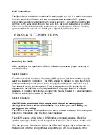
Cat5 Connections
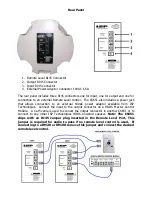
The figure below shows the connections for each output A, B and C of each zone output
on the Master Control Module and also connections between each CS651 speaker.
Connections are done via standard Cat5 cables where pins 1 through 8 are connected
common to the same pins 1 through 8 at each end. As shown below two wires in the
Cable are used for balanced audio and 6 wires are used for power with two providing
ground and two for each of two 22VAC power signals fed down the cable.
Mounting the CS651
Refer installation to a qualified installation professional to ensure proper mounting to
overhead ceilings.
Speaker Location
To achieve the best performance from the CS651 speakers, it is important to carefully
select the location for installation. The CS651 should be installed no more than 5 feet
center to center to provide proper stereo imaging if used in stereo or to avoid comb
filter issues if used in a mono system. The coverage pattern is 90 degrees by 90
degrees with the CS651 so ceiling height will affect the proper location of multiple
speakers. If installing the CS651 as a Single Point Source Speaker it is recommended to
install the speaker in the center of the room.
Speaker Installation
CAUTION: Be certain that there are no electrical wires, water pipes or
heating ducts in the planned installation area before you start drilling or
cutting into the ceiling.
The CS651 is designed to be installed in the ceiling between the studs. If mounting the
CS651 in a drop ceiling other bracing is recommended.
The CS651 requires a hole cutout of 9 5/8 inches for proper clearance. Check the
speaker opening by placing one of the speakers in the hole. The speaker should easily
fit in the opening. Remove the grill on the CS561 with a paper clip or other small tool
that will insert into the small grill holes and pull the grill off. You can also turn the

