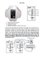
The power connection on the back of the CS651 can be used to power the speaker as a
stand-alone speaker or can also be used to add additional power if a long run of Cat5
cable is used. When powered a Blue LED will illuminate behind the front grill of the
CS651 indicating the unit is active. The system is designed to allow use of both the
Cat5 cable connected to the HDDS Master Control Module and also an external adaptor
at the same time without risk of damage. The internal power supply will simply derive
power for the power source with the highest voltage available at any point in time.
The CS651 will typically pull less than 250 milliamps of current from the output of the
Master Control Module when used at typical listening levels. With a typical 5 watts of
power per speaker a maximum of 12 CS651 ceiling speakers can be serially connected
on a single run of Cat5 cable. At maximum output level of 30 watts the CS651 can
pull in excess of 1 amp of current. If the installation requires maximum output power it
is recommended to limit the number of serially connected CS651 speakers on a single
50ft run of Cat5 cable to no more than 5 speakers. With longer runs of cable the total
number of CS651 ceiling speakers needs to be reduced in order to achieve a full 30
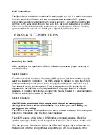
watts continuous output power. Connect the CS651 to any of the three A,B or C
outputs on the rear of the HDDS Master Control Module as shown above.
SPEAKER POWER
The HDDS system distributes low voltage Alternating Current over the Cat5 cable plus
high level balanced audio and is capable of greater than 30 watts continuous power per
speaker. With a typical power per speaker of 10 watts each speaker will consume on
the order of 400mA, which means that 12 speakers would require 4,800mA of current.
Installed systems that require more output power per speaker simply require that the
number of speakers per output A, B and C be reduced so as not to exceed the
maximum of 7 amps available. The current consumption at full power (30 watt
continuous) will require over 1 Amp of power per speaker. In order to allow the full 30
watts of power where higher output levels are required, the number of speakers per A,
B and C outputs of each zone needs to be limited to a maximum 5. Reducing to 20
watts of power per speaker, a maximum of 8 speakers per output can be connected to
each A, B and C zone output. With longer runs of cable exceeding 150 feet the cable
voltage drop will start to become a design factor. The Cat5 cable will start to limit the
total power capability once you exceed 75 feet of cable. Where maximum power
output is critical a more precise calculation can be done by following the speaker
consumption guide.

