Specialty Applications - See Thru
44
FIGURE 80
FIGURE 81
FIGURE 82
The Fire-Lite Series see-thru fireplace is built
from the Fire-Lite Series 36” fireplace and is available
in a model 36.
Please note that due to the large opening area of a
two-sided fireplace this type of fireplace can be difficult to get
to reach and to maintain proper drafting.
Drafting formulas indicate that 14” diameter flue is
large enough to support a two sided Fire-Lite Series 36” fire
-
place if the unit has at least 24’ of flue. This, however, is no
guarantee of draft performance.
Constructing a Fire-Lite See -Though Unit:
Set the base plate as with the Fire-Lite Series unit.
The firebox back wall components are not used. The
firebox side walls are set, reversed from their normal position,
their flared faces set to the outside of the fi rebox. (Figure 80)
The firebox side walls must sit a full 3” on the front
& rear of the base plate. Since the side wall components flair
from 3” at the narrow front end to 8” on the wide rear end, the
side walls will overhang the base plate by approximately 5” at
the rear of the unit. (Figure 82)
Once the side wall assembly is complete it is
necessary to place a steel angle minimum 4”x4”x3/8” across
each face of the two sided opening before building the smoke
dome assembly. Notch the ends of each sidewall equal to the
thickness of the steel as shown. Each end of the steel angles
must bear fully at least 3” onto the side wall assembly.
(Figure 80)
Since there is no back wall assembly and no side wall
ledge for placement of a cast iron throat damper, the smoke
dome for the Fire-Lite Series see-thru 36” fireplace is
built by placing one long damper beam on top of the firebox
back wall and flush with it; the other long damper beam sits
flush with the front of the firebox, spanning the firebox open
-
ing.
These components both sit on their narrow base so
that their beveled face points down and into the firebox interior.
The damper plate end pieces are designed to sit on
the fi rebox side wall between the front and back long damper
beams. Place the vertical face of each piece (S64L & S64R)
1-1/2” to the inside of the inside sidewall of the fi rebox. This
will allow the fi rebrick to align fl ush with the damper end
pieces.
Once the smoke dome assembly is built and the
DM 54 chimney is installed, a chimney top damper is set
at the top of the flue.
Inside height 30”
Inside width 33”
Outside width 53”
Thru-wall 25 1/4”
Rough Opening: 56” wide x 79” high
Содержание FIRE-LITE series
Страница 7: ...Assembled Firebox Smoke Dome Dimensions 36 42 46 7 ...
Страница 23: ...23 Interior Masonry Veneer Fireplace Finishes Clearances FIGURE 38 FIGURE 36 FIGURE 37 ...
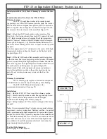
Страница 28: ...DM 54 Chimney Component List Dimensions 28 ...
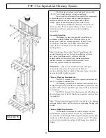
Страница 32: ...32 DM 54 Chimney System Lateral Support cont FIGURE 51 FIGURE 52 ...
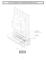
Страница 51: ...51 Fire Lite Application Raised Metal Platform cont FIGURE 93 ...
Страница 58: ...Notes 58 ...


