background image

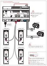
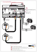
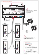
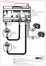
2. ATLAS INSTALLATION

Connect to 

192.168.0.184

 from 

Google Chrome, 

Microsoft Edge 

or Apple 

Safari 

Internet browser.

Lift up and remove 
the white cover

1

Move the jumper on 

Battery ON

2

Check the green 
Power IN LED is ON

4

Lockbus 

channel

RS485

channels

Onboard

Relays

ATLAS DIN 

PoE

Console

Battery

ON

Reset

W

ake up

Switch OFF

ON

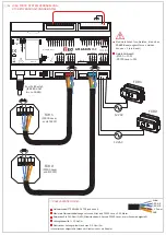
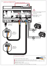
GND

+5V 

+V OUT

OUT 1

IN  1

GND

 Analog IN

GND

+V Power

GND

SER. A

SER. B

COM

NO

NO

COM

R

USB

CH0

Relay

1

Relay

2

IN  2

IN  5

IN  3

IN  4

GND

+5V 

R  1

R  3

LED  2

LED  1

R  2

R  5

R  4

+V Power

GND

SER. A

SER. B

CH1

AUX

+V Power

GND

SER. A

SER. B

CH2

Power IN

12 VDC - 800 mA

24 VDC - 400 mA

MADE IN ITALY

PoE

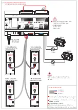
Connect the CAT5e/CAT6 
Ethernet cable coming from 
the

 Switch PoE (cable and 

switch PoE not included)

3

(Wire connected between 

+V OUT and +Power IN)

To PoE Switch 

(IEEE 802.3af

up to 15,4W)

DO NOT REMOVE!

Color

Green
Red
Orange

Description

Power IN active
Switch OFF

Backup battery
pack operating

Orange
Orange
Orange
Orange

Ethernet activity
Serial Tx/Rx CH0

Serial Tx/Rx CH1
Serial Tx/Rx CH1

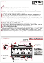
LED reference table

Ref.

ON
OFF
BATT

ETH
TX/RX
TX/RX
TX/RX

ON

OFF

BATT

ETH

TX/RX

TX/RX

TX/RX

For future

developments

Battery

ON

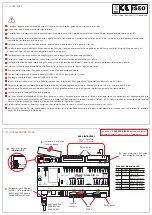
WARNINGS

https://www.iseo.com/it/en/download

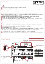
Read this manual prior to use the device in order to ensure a safe and proper use.

Preserve this manual as future reference.

The installation and maintanance of the device must be carried out by qualified technical staff, adequately trained by ISEO.

The instructions should be carefully followed during installation. These instructions and any maintenance instructions should be passed on by the installer 
to the user.

No modifications of any kind are permitted, except for those described in these instructions.

The product must be destined only for the use for which it is expressly designed and therefore as web server controller for civil and industrial locations. 
Any other use is considered improper and dangerous.

The electrical connection must be made according to the constructor's instructions and respecting the regulations in force.

For all repairs, exclusively contact a technical assistance center authorized by the constructor.

Disconnect the power supply before carrying out any technical service that involves opening or accessing the internal parts of the product.

Dispose of the product separately from household waste, in accordance with local laws and regulations.

Ensure full recharge of the Atlas internal battery by running a full recharge cycle (24 hours), minimun every 6 months.

The calculation of the cables section must be performed by qualified staff.

Max cable length of LOCKBUS channel is 100 mt (sum of all branches). 

Recommended voltage for LOCKBUS channel is 24 VDC.

In case of power failure the rechargeable battery inside the Atlas ensure power for 30 minutes max.

It is advisable to provide for an appropriate sectioning, a protection switch upstream of the transformer.

For any technical assistance or repairs, contact only

 Iseo Serrature

 or an 

Iseo Zero1 

authorised technical centre.  

Iseo Zero1

 reserves the right, without prior notice, to make all the necessary modifications to the product and to the instruction manual, for quality 

improvements or manufacturing or marketing needs.

Atlas earth connection is mandatory.

Add Surge Protection Devices (SPD) to the mains, upstream the Atlas Master, when connected to Atlas Slaves, Actuators and Readers placed in outside 
areas of the builing (not equipotential zones), according to the Lightning Protection Risk Assessment of your building and current legislations.

Содержание Zero1 Atlas Plus

Страница 1: ... 50 C Storage temperature 20 C 70 C Conformity certifications 2014 53 EU RED RoHS electrical and electronic equipment References standards EN301 489 1 EN301 489 17 EN330 440 EN60950 1 EN62209 2 For details see Declarations of Conformity available at iseo com website download area Package contents 1 Atlas Plus DIN Server for RFID and F9000 ON LINE and OFF LINE devices with connectors Installation g...

Страница 2: ...escribed in these instructions The product must be destined only for the use for which it is expressly designed and therefore as web server controller for civil and industrial locations Any other use is considered improper and dangerous The electrical connection must be made according to the constructor s instructions and respecting the regulations in force For all repairs exclusively contact a te...

Страница 3: ... 3af up to 15 4W 12 VAC 12 VAC DOOR 1 Back side view circuit board DOOR 1 IN Stylos cod 5E1310126 S1 DOOR 2 Total LOCKBUS channel cable length sum of all branches MAX 100mt Conductor capacitance 100pF m Conductors electrical resistance max 90 ohm Km Cable 3 x 0 75mm AWG 18 the calculation of the cables section must be verified by qualified staff WIRING SPECIFICATIONS LOCKBUS V ALIM GND DOOR 2 IN S...

Страница 4: ...ND SER A SER B CH1 AUX V Power GND SER A SER B CH2 Power IN 12 VDC 800 mA 24 VDC 400 mA MADE IN ITALY PoE WIRING SPECIFICATIONS Maximum Ethernet cable length between Atlas and F9000 Reader 500mt Ethernet cable FTP AWG24 CAT5E and above Connect 120 ohm 1 4W resistor on both Atlas and F9000 Reader sides as shown in the scheme Conductor capacitance 100pF m Conductors electrical resistance max 90 ohm ...

Страница 5: ...atura di operatività 10 C 50 C Temperatura di stoccaggio 20 C 70 C Certificazioni di conformità 2014 53 EU RED RoHS apparecchiature elettriche ed elettroniche Standard di riferimento EN301 489 1 EN301 489 17 EN330 440 EN60950 1 EN62209 2 Per dettagli consulta le Dichiarazioni di Conformità disponibili sul sito web iseo com area download Contenuto della confezione Server Atlas Plus DIN per disposit...

Страница 6: ...quale è espressamente progettato e quindi come controller di server Web per sedi civili e industriali Ogni altro uso è considerato improprio e pericoloso Il collegamento elettrico deve essere eseguito secondo le leggi vigenti da personale qualificato Per tutte le riparazioni contattare esclusivamente i centri di assistenza tecnica autorizzati dal costruttore Scollegare l alimentazione prima di ese...

Страница 7: ...12 VAC PORTA 1 PORTA 1 IN Stylos cod 5E1310126 S1 PORTA 2 PORTA 2 IN Stylos cod 5E1310126 PORTA 1 OUT Stylos cod 5E1310126 S1 PORTA 2 OUT Stylos cod 5E1310126 Lunghezza totale dei cavi collegati al canale LOCKBUS somma di tutti i rami MAX 100 mt Capacità conduttore 100 pF m Resistenza elettrica del conduttore max 90 ohm Km Cavo allarme 3 x 0 75mm AWG 18 il calcolo della sezione dei cavi deve esser...

Страница 8: ...LY PoE Allo Switch PoE IEEE 802 3af fino a 15 4 W 4 CABLAGGIO SISTEMA V364 F9000 ESEMPIO DI CONNESSIONE PER LA GESTIONE DI 2 PORTE PORTA 2 Lettore F9000 cod E03222 PORTA 1 Lettore F9000 cod E03222 12 VAC 12 VAC PORTA 1 PORTA 2 SPECIFICHE CABLAGGI Massima lunghezza del cavo Ethernet tra Atlas e Lettore F9000 500 mt Cavo Ethernet FTP AWG24 CAT5E o superiore Collegare una resistenza da 120 ohm 1 4 W ...

Страница 9: ...en Umweltbedingungen Betriebstemperatur 10 C bis 50 C Lagertemperatur 20 C bis 70 C Konformitätserklärungen 2014 53 EU RED RoHS elektrische und elektronische Geräte Normen EN301 489 1 EN301 489 17 EN330 440 EN60950 1 EN62209 2 Weitere Details zu Konformitätserklärungen sind unter www iseo com verfügbar Verpackungsinhalt 1 Atlas Plus DIN Controller für RFID und F9000 ONLINE und OFFLINE Geräte inkl ...

Страница 10: ... nur zu dem Zweck verwendet werden für den es konzipiert wurde anderweitiger Gebrauch gilt als unsachgemäß und ist gefährlich Die elektrischen Anschlüsse sind entsprechend den Anweisungen in dieser Anleitung vorzunehmen und müssen den geltenden Vorschriften entsprechen Wenden Sie sich für alle Reparaturen ausschließlich an einen vom Hersteller autorisierten technischen Fachhändler Unterbrechen Sie...

Страница 11: ... zu 15 4W 12 VAC 12 VAC TÜR 1 Rückansicht Leiterplatte TÜR 1 EINGANG Stylos cod 5E1310126 S1 TÜR 2 Gesamte LOCKBUS Kanal Kabellänge Summe aller Zweige Maximal 100 Meter Leitungskapazität 100pF m Elektrischer Leitungswiderstand max 90 Ohm Km Kabel 3 x 0 75mm AWG 18 die Berechnung des Kabel querschnitts muss durch qualifiziertes Personal erfolgen KABEL SPEZIFIKATIONEN LOCKBUS V ALIM GND TÜR 2 EINGAN...

Страница 12: ... GND SER A SER B CH1 AUX V Power GND SER A SER B CH2 Power IN 12 VDC 800 mA 24 VDC 400 mA MADE IN ITALY PoE KABEL SPEZIFIKATIONEN Maximale Netzwerkkabel Länge zwischen Atlas and F9000 Leser 500 Meter Netzwerkkabel FTP AWG24 CAT5E und höher Verwenden Sie 120 Ohm 1 4W Widerstände am Atlas und F9000 Leser wie im Schema dargestellt Leitungskapazität 100pF m Elektrischer Leitungswiderstand max 90 Ohm K...

Страница 13: ... x H 160 x 90 x 60 mm 9 modules Caractéristiques environnementales Température de fonctionnement 10 C 50 C Température de stockage 20 C 70 C Certificats de conformité 2014 53 EU RED RoHS electrical and electronic equipment Références standards EN301 489 1 EN301 489 17 EN330 440 EN60950 1 EN62209 2 Pour plus de détails voir les certificats de conformité disponible sur le site iseo com dans téléchar...

Страница 14: ...ructions du constructeur et dans le respect de la réglementation en vigueur Pour toute réparation adressez vous exclusivement à un centre d assistance technique agréé par le constructeur Débrancher l alimentation électrique avant d effectuer une maintenance technique qui implique l ouverture ou l accès aux parties internes du produit Jeter le produit séparément des déchets ménagers conformément au...

Страница 15: ...PORTE 1 IN Stylos réf 5E1310126 S1 PORTE 2 PORTE 2 IN Stylos réf 5E1310126 PORTE 1 OUT Stylos réf 5E1310126 S1 PORTE 2 OUT Stylos réf 5E1310126 Vue arrière de la plaque de câblage intégrée Vue arrière de la plaque de câblage intégrée Vue arrière de la plaque de câblage intégrée Vue arrière de la plaque de câblage intégrée Longueur totale du câble du circuit LOCKBUS somme de tous les câbles MAX 100...

Страница 16: ...1 AUX V Power GND SER A SER B CH2 Power IN 12 VDC 800 mA 24 VDC 400 mA MADE IN ITALY PoE PORTE 2 Lecteur F9000 réf E03222 PORTE 1 Lecteur F9000 réf E03222 12 VAC 12 VAC PORTE 1 PORTE 2 Vers le passage PoE IEEE 802 3af jusqu à 15 4W SPÉCIFICATIONS DE CÂBLAGE Longueur maximale du câble Ethernet entre l Atlas et le lecteur F9000 500mt Câble Ethernet FTP AWG24 CAT5E et supérieur Connecter une batterie...

Страница 17: ...0 para conectar online lectores Stylos y Actuadores máx 8 8 para Atlas DIN y máx 4 lectores solo para Atlas DIN PoE 2 canales RS485 CH1 CH2 para conectar online lectores F9000 máx 1 por canal 1 USB 2 0 Tipo A 1 interfaz en serie debug Fuente de alimentación 12 24 Vcc o PoE Consumo máximo 10W sin dispositivos conectados Fuente de alimentación PoE Requiere Switch PoE IEEE 802 3af hasta 15 4W Potenci...

Страница 18: ...or el constructor Desconecte la fuente de alimentación antes de realizar cualquier servicio técnico que implique abrir o acceder a las partes internas del producto Deseche el producto por separado de la basura doméstica de acuerdo con las leyes y regulaciones en vigor Garantire la ricarica completa della batteria interna dell Atlas eseguendo un ciclo di ricarica completo 24 ore minimo ogni 6 mesi ...

Страница 19: ...ERTA 1 PUERTA 1 ENTRADA Stylos cod 5E1310126 S1 PUERTA 2 PUERTA 2 ENTRADA Stylos cod 5E1310126 PUERTA 1 SALIDA Stylos cod 5E1310126 S1 PUERTA 2 SALIDA Stylos cod 5E1310126 Vista posterior del circuito Vista posterior del circuito Vista posterior del circuito Vista posterior del circuito Para la configuración de la dirección del Stylos consulte la Guía de instalación de Stylos disponible en iseo co...

Страница 20: ...E Al Switch PoE IEEE 802 3af hasta 15 4 W 4 CABLEADO DEL SISTEMA V364 F9000 EJEMPLO DE CONEXIÓN DEL CONTROLADOR DE 2 PUERTAS PUERTA 2 Lector F9000 cod E03222 PUERTA 1 Lector F9000 cod E03222 12 VAC 12 VAC PUERTA 1 PUERTA 2 ESPECIFICACIONES DEL CABLEADO Longitud máxima del cable Ethernet entre Atlas y lector F9000 500m Cable Ethernet FTP AWG24 CAT5E y superior Conecte una resistencia de 120 ohm 1 4...

Отзывы: