MD24 / MD28
– Hardware Description
10
9.2 Multiple Drivers
It is recommended to have multiple drivers to share one power supply to reduce cost, if
the supply has enough capacity. To avoid cross interference,
DO NOT
daisy-chain the
power supply input pins of the drivers. (Instead, please connect them to power supply
separately.)
Attention:
NEVER connect power and ground in the wrong direction, as it will damage
the M24/MD28.
10 Selecting Microstep Resolution and Driver Output Current
This driver uses an 8-bit DIP switch to set microstep resolution, and motor operating
current, as shown below:
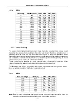
10.1 Microstep Resolution Selection
Microstep resolution is set by SW5, 6, 7, 8 of the DIP switch as shown in the following
tables:
10.1.1
MD24
Microstep
Steps/rev.
SW5 SW6 SW7 SW8
2
400
OFF
ON
ON
ON
4
800
ON
OFF
ON
ON
8
1600
OFF OFF
ON
ON
16
3200
ON
ON
OFF
ON
32
6400
OFF
ON
OFF
ON
64
12800
ON
OFF OFF
ON
128
25600
OFF OFF OFF
ON
5
1000
ON
ON
ON
OFF
10
2000
OFF
ON
ON
OFF
20
4000
ON
OFF
ON
OFF
25
5000
OFF OFF
ON
OFF
40
8000
ON
ON
OFF OFF
50
10000
OFF
ON
OFF OFF
100
20000
ON
OFF OFF OFF
125
25000
OFF OFF OFF OFF


