iBC 10
– Hardware description
7
3
Connections
3.1
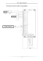
Connection for power supply (X1/Power IN)
Here the output of the DC-power supply unit is connected. This is decoupled via a
diode from the outputs of the final stages.
3.2
Connection for final stages (X1/Power OUT)
The final stages are affiliated to the above-mentioned diode decoupled voltage. Up
to 5 final stages can be connected. However, the permissible total current
of 15 A must not be exceeded. Short-term peak loads are permitted.
3.3
Distributor (X2/A,B)
These connectors are for internal use only. The pin "A" and "B" are each bridged.
Here, for example, fans can be clamped in parallel.
3.4
Fault-Output (X2/C,E)
The terminals C and E are used for internal temperature monitoring. If the terminal
C connected to +24 V, thus leading to the terminal E +24 V, as long as the
temperature limit is not exceeded. Upon reaching the shutdown temperature of 75
° C, the temperature monitoring interrupts a24 V -> 0V at terminal E. After
cooling, the sensor switches itself back on -> +24 V at terminal E.
The connection should be wired to use the internal monitor the temperature.


