9
ASSEMBLY INSTRUCTIONS
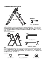
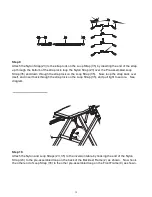
Step 1
Stand up the base of the machine by separating the frames
as shown above. Pull the Rear/Front
Frames (8, 9) as far apart as possible from each others and align the pin holes. Then insert the
Ø8x63.5mm Ring Pin (26) from inner side into the holes on the Rear/Front Frames (8, 9) to lock the
frames in place.
․․․․․․․․․․․․․․․․․․․․․․․․․․․․․․․․․․․․․․․․․․․․․․․․․․․․
․․․․․․․․․․․․․․․․․․․․․․․․․․․․․․․․․․․․․․․․․․․․․․․․․․․․
․․․․․․․․․․․․․․․․․․․․․․․․․․․․․․․․․․․․․․․․․․․․․․․․․․․․
․․․․․․․․․․․․․․․․․․․․․․․․․․․․․․․․․․․․․․․․․․․․․․․․․․․․
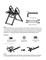
Step 2
Attach the Handlebar (6) onto the Rear Frame (8) with two M8x60mm Hexagon Socket Head Cap
Bolts (20), two M8 Nut Caps (24), and four Ø16xØ8.5x1.5 Flat Washers (19). Tighten bolts and
nut caps with the provided Wrench and Allen Wrench. Repeat above same step to attach the other
Handlebar (6) onto the Rear Frame (8).
Hardware:
6
20
20
19
24
24
19
19
8
6
Tool:
1 Allen Wrench #6
1 Wrench (#13 & #17)
8 Flat Washers
(Ø16xØ8.5x1.5)
4 Nut Caps (M8)
4 Hexagon Socket Head
Cap Bolts (M8x60mm)
1 Ring Pin (Ø8x63.5mm)
Hardware:
8
9
26
Содержание 5501
Страница 5: ...4 WARNING LABEL PLACEMENT ...

