background image

C

OMPUTER

 O

PERATION


P

AGE

 16 


P

P

ROGRAMMING

ROGRAMMING


THE

THE


C

C

OMPUTER

OMPUTER


S

ELECT

  T

RAINING

 P

ROGRAM


T

HE

 5 

AVAILABLE


PROGRAM


MODES

AS


LISTED


BELOW

 (M

ANUAL

, P

ROGRAM

, T

ARGET

 H

EART

 R

ATE

, U

SER

AND

 W

ATT

), 

WILL


APPEAR


AS


SCROLLING


TEXT


IN


THE


DISPLAY


WINDOW

. S

ELECT


ONE


OF


THE


TRAINING


PROGRAMS

 (

LISTED


BELOW

USING


THE

 UP, DOWN 

BUTTONS

. P

RESS


THE


ENTER 

BUTTON


TO


LOCK


IN


THE


DESIRED


PROGRAM


MODE

. P

RESS


THE

 START / STOP 

BUTTON


TO


BEGIN


TRAINING


IN


THE


DESIRED


MODE


OR


USE


THE

 UP / DOWN 

BUTTONS


TO


CONTINUE


THE


PROGRAM


SELECTION

.  

♦ 

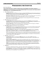
M

ANUAL

 M

ODE


(Standard Program)


Activation Procedure: 1) 

Press the ENTER button to start program set up. 

2) 

Use the UP / DOWN buttons to adjust the resistance level and press the 

ENTER button to set the desired level (see reference below) or press the START/STOP button to begin training.  

3) 

Use the UP & DOWN   buttons to 

preset (adjust) individual target training time or press the START / STOP button to begin training. 

Manual Resistance Adjustment: 

The display will reference 1-16 levels of training resistance. Level 16 will be highest resistance setting. Use The Up, 

Down buttons to select a desired resistance setting. The display graph will change as resistance levels are changed (adjusted).  

Note

: Resistance levels will  automatically adjust to match preprogrammed or customized  training profiles. Resistance can  be manually adjusted  

during by training by pressing the UP or DOWN buttons.  

♦ 

P

ROGRAM

 M

ODE


(Preprogrammed Training Profiles)  


Activation Procedure: 1) 

Press the “UP” button until the Program mode is selected. 

2) 

Press the ENTER button  

3) 

Select Training Profile 

(referenced below)  

4) 

Press the UP/DOWN button to adjust the target training time or press the START/STOP button to begin training.  

5) 

Press the 

UP/DOWN button to adjust the training resistance or press the START/STOP button to begin training.  


Selecting a Training Profile: 

The computer has 12 programmed resistance (training) profiles (P1-P12). Press the UP button to scroll through the 


training profiles.  Once a training profile is selected, press the ENTER button to lock in the profile.  

♦ 

T

ARGET

 H

EART

 R

ATE

 M

ODE


(Training Profile Based on Target Heart Rate Zones)


Activation Procedure: 1) 

Press the “UP”  button until the Target Heart Rate program mode is selected.  

2) 

Press the “Enter” button  

3)

 Press the UP/     


DOWN buttons to preset your age, press the ENTER button. 

4) 

Select a heart rate training zone (referenced below) 

5) 

Press the START / STOP        


button to begin training or use the UP & DOWN buttons to adjust the training target time. 


Setting a HR Training Zone: 

Zone training is based on exercising within a set percentage of a users maximum heart rate. A users maximum        


heart rate is based on a simple formula;  (220 BPM  -  Users Age = Maximum HR).  Use the UP/DOWN buttons to select one of the HR (zone)      


training percentage referenced in the lower display. (55%, 75% or 90% ) and press the ENTER button to lock in the zone setting.  


Note

: The resistance will auto-adjust according heart rate presets. If a user’s heart rates falls under the preset targets, the resistance auto- adjust up one        


 level every 30-seconds until target rate is achieved. If a users heart rate exceeds the target presets, the computer will auto-adjust down the resistance             


 one level until target is  reached. For training safety, the computer will stop functioning and beep, if a user continues to exceed a target heart rate for    


more than 30-seconds at the lowest resistance training level. 

♦ 

U

SER

 M

ODE


(Customized Training Grid)


Activation Procedure: 1) 

Press the “UP” button until the “

USER

” program mode is selected. 

2) 

Press the ENTER  button  

3) 

Set a          


customized training . Profile (referenced below). 

4) 

Press the UP/DOWN buttons to adjust the target training time.  

5) 

Press the START / STOP         


 button to begin training. 

Setting a Customized Training Profile: 

The lower display will reference 16 individual  profile (resistance) columns. Each column can be set to   an 

individual  resistance level (1-16). The UP , DOWN buttons will adjust the number resistance bars (segments) per column.  After an individual      
column has been preset (adjusted),  press the ENTER button. Continue the set up process until all 16 columns have been customized (preset) and a  full 
training profile exist. Once a profile is set, press the Start / Stop button to begin training  or press the Enter button to set desired function targets. 


NOTE: 

Once a preset function has been reached (counts down to zero ), the computer will beep to alert the user a preset goal has been achieved.       


All display functions will stop once a single preset goal has been reached. A user may continue training after an individual function target has been 


achieved, by pressing the START / STOP button. At that point, all values will count up from zero. 

♦ 

WATT M

ODE


In this program, the WATT function will keep a constant value. This means that if you pedal quickly, the tension will decrease, if 


you pedal slowly the tension will increase to maintain the Watt value entered. Use the UP/DOWN buttons to scroll to this program. 


Press MODE/ENTER to select this program. WATT will flash in the display. Use the UP/DOWN keys to set desired WATT. Press 


MODE/ENTER to confirm value. Repeat steps for DISTANCE, CALORIES and PULSE. Press START/STOP to begin exercising. 


Grasp Pulse Grips loosely with both hands to activate PULSE function. 

Содержание 1880

Страница 1: ...FORFUTUREREFERENCE S S S SAFETY AFETY AFETY AFETY PROPERLYWARMUPAND STRETCHBEFOREEXERCISING IFYOUFEELPAINORDIZZINESSAT ANYTIMEWHILE EXERCISING STOP IMMEDIATELYANDCONSULT YOURPHYSICIAN SERIAL NO SERIAL NO SERIAL NO SERIAL NO _____________________________________________ PURCHASE DATE ____________________ PURCHASE DATE ____________________ PURCHASE DATE ____________________ PURCHASE DATE ___________...

Страница 2: ...nit 7 Allowproperspace for useand setup of theequipment Usecarewhen mounting and dismounting equipment 8 It s recommended to placeanexercise product matbeneath theequipment foradded protectionoffloorsorcarpets 9 Inspectproductona frequentbasis Tighten loose assembliesorhardware as needed Replace wornordamaged parts 10 Wearproperworkout apparel Avoid wearing looseclothing ordangling shoe lacesdurin...

Страница 3: ...Note Afterassemblyiscompleted allow aminimalof 2 3ft ofspaceoneachsideofunitforuseraccessanddismounting Thebasictoolsforassemblingthisproductareincludedwithmainassemblyhardware Donotdisposeof anypackagingmaterialsuntilassemblyoftheproductiscompleted If youexperienceproblemswithoperationoftheequipmentafterassembly pleasereviewthe troubleshootingreferencepageinthismanual Makesuretocompletelyfill out...

Страница 4: ...LAT WASHER 8 X 16X 1T 2 50 02166 LEVELER 2 51 02165 JAM NUT 2 52 IM07394 ROLLER COVER LEFT 2 53 IM07393 ROLLER COVER RIGHT 2 Item Part Description QTY 1 N A BASE ASSEMBLY 1 2 IM23273 FRONT STABILIZER ASSEMBLY 1 3 IM05444 SIDE STABILIZER EXTENSION ASSEMBLY 2 4 IM23783 HANDLEBAR MAST ASSEMBLY 1 5 12216 UPPER DATA CABLE 1 6 12217 LOWER DATA CABLE 1 7 IM0744909 LEFT MAST COVER 1 8 IM0744809 RIGHT MAST...

Страница 5: ...lt 2 Pcs Hex Bolt 2 Pcs Hex Bolt 2 Pcs Flat Washers 10 x 26 x 2t Flat Washers 10 x 26 x 2t Flat Washers 10 x 26 x 2t Flat Washers 10 x 26 x 2t 2 pcs 2 pcs 2 pcs 2 pcs Flat Washers 17 5 x 25 x 3t Flat Washers 17 5 x 25 x 3t Flat Washers 17 5 x 25 x 3t Flat Washers 17 5 x 25 x 3t 4 pcs 4 pcs 4 pcs 4 pcs 3 8 Lock Nut 3 8 Lock Nut 3 8 Lock Nut 3 8 Lock Nut 2 Pcs 2 Pcs 2 Pcs 2 Pcs Flat Washers 10 x 26 ...

Страница 6: ...6 15 4 23 22 18 31 32 49 34 33 30 48 41 3 39 37 39 37 34 43 39 41 37 35 39 45 31 39 39 C CUSTOMER USTOMER S SERVICE ERVICE 1 877 788 9991 1880 P 1880 PARTS ARTS 3 5 6 7 20 24 25 26 25 26 27 28 38 31 37 39 12 39 40 42 44 43 37 39 29 46 47 36 37 37 10 9 5 ...

Страница 7: ...ing4 Carriage Bolts 35 4 CurvedWashers 31 and 4 AcornNuts 34 asshownabove AssemblyNotes UsetheAdjustableLevelers 50 located onthe bottomoftheStabilizer End Caps toleveltheequipmentand preventthe base unitfromrockingon anuneven surface Locktheheightadjustmentinplace bytighteningtheJamNut IMPORTANT Make sureto usetheenclosedlubricanttocoatthebaserails This willsmooththetravel ofthe pedal movement as...

Страница 8: ...6 asshown inFIGURE 1 C Tuckthecable lengths insidetheframe tubesandinserttheend oftheHandlebarMastAssembly 4 down ontotheBase Assembly 1 Alignthe mountingholes and securethe mast assemblyin placeusing5 ButtonHead 3 1 Bolts 36 D Attachthe Left RightMastCovers 7 8 usingacombination 4 Self ThreadingScrews 37 and 2 Self Threading Screws 38 followingthe orientationshown AssemblyNote Usecautionwhenassem...

Страница 9: ...oftheComputer Note Avoidpullingon stretching thecableassembliesinordertomakecomputerconnections ReferenceFIGURE 2 C ConnecttheplugendoftheHeartRateCable 9 intothereceptacleendoftheofthecable pigtail comingfromthebackof theComputer ReferenceFIGURE 2 D Tuckexcesscablelengthsdownintothemastand placetheComputer 10 ontopofthemountingplate AligntheBacking Plate 11 andsecuretheComputer 30 totheHandlebarM...

Страница 10: ...theendof thePivotShaft 12 Secure the armto theshaft using1 Teflon Washer 42 1 FlatWasher 41 and1 HexHeadFlangeBolt 40 followingtheorientationshown Note Loosely tighten the Hex Bolt untilthe Right SwingArmisin place C Repeatthe assemblyreference forattachingtheRightSwingArmAssembly 14 tothePivotShaft 12 Securethearmin placeusing1 TeflonWasher 42 1 FlatWasher 41 and1 HexBolt 40 followingtheorientati...

Страница 11: ...edinthe assemblylocation andnot includedas partofthe packaged assemblyhardware A Alignthe UpperPivotCovers 17 18 19 20 withthecorrespondingpivotareasof eachSwingArm Assemblethe coversas shown usinga combinationof 2 Self ThreadingScrews 37 and1 TrussScrew 39 per side B AttachtheBottleCage 27 totheHandlebarMast 4 usingthe2 preinstalledTrussScrews 39 Oncethecagehasbeen mounted inserttheSportsBottle 2...

Страница 12: ...led proceed ontothenextassemblystep Iftheyarenotinstalled followtheassemblyinstructionlistedbelow Some ofthe mountinghardware maybepreinstalledinthemountingareasoftheassemblyparts Iftheneededhardwareisnotpartoftheenclosedhardwarepack checktheactual mountingarea ontheassemblypart A AttachRollerArmPivotCovers 21 22 23 24 totheRollerArmAssembliesusing2 TrussScrews 39 and 2 Self ThreadingScrews 37 per...

Страница 13: ...ttonHeadBolt 45 1 FlatWasher 41 1 FlatWasher 46 and 1 3 8LockingNut 47 perarmassembly B Connect thelower mountingareaofthe Left RightSwingArmAssemblies 13 14 to thecorresponding PedalArm Assemblies 15 16 using1 ButtonHeadBolt 48 1 FlatWashers 49 and1 M8LockingNut 32 C OncethePedal Arms aresecured attach theLowerLeft RightJointCovers 25 26 over eachjointconnection Use a combinationof 1 Self Threadi...

Страница 14: ...tupon pluggingitintothewallorproduct stopusageimmediately Shortedadapterswillneedtobereplaced Thereceptacle shroud locationwillvaryperproduct model ArrangeplacementoftheunitsotheACadaptercaneasilyreach thereceptacleandanoutletplug Assembly Description A PluginthecordendoftheACAdapter 29 intothereceptaclelocatedonfrontorbackoftheBaseAssembly shroud B PlugtheACAdapterintoanavailablewalloutlet Safety...

Страница 15: ...TOSTART TRAINING ALLOTHERCOMPUTERFUNCTIONSWILLCOUNTUPFROM 0 RESISTANCE BIKEISEQUIPPEDWITHANADJUSTABLERESISTANCEMECHANISM THISFEATUREWILL ALLOW AUSERTO CHOOSEFROM1 16LEVELSOFVARIEDRESISTANCE AUSERCANADJUSTRESISTANCE ATANYTIMEDURINGATRAININGMODEBYPUSHINGTHE UP or DOWN BUTTON EXCEPTIN TARGETHEARTRATEMODE BUTTONFUNCTIONS ENTER SELECTS SETSDISPLAYFUNCTIONS START STOP ACTIVATES STOPSCOMPUTERFUNCTIONS UP...

Страница 16: ...RATEREADING ABLINKINGHEARTSYMBOL NUMERICREADING WILLBEDISPLAYEDONTHECOMPUTERASLONGASAUSER SHANDSARELOCATEDONTHEGRIPSENSORS READINGSWILL APPEARWITHIN30SECONDS TO1MINUTEOFCONSISTENTGRIP CONTACT READINGSWILL BECOMEINCONSISTENTIFAUSERFAILSTOLEAVEBOTHHANDSINCONTACTWITHTHEGRIPSENSORS PRESETATARGETHEARTRATE ATARGETHEARTRATEWILL BEPRESETWHENUSINGONEOFTHEFOUR TARGETHEARTRATEPROGRAMS PULSESETTINGSWILLBEFROM...

Страница 17: ...one Zonetrainingisbased on exercising within a setpercentageofausers maximumheartrate Ausers maximum heartrate isbased on asimple formula 220 BPM Users Age MaximumHR Usethe UP DOWNbuttonsto selectoneofthe HR zone trainingpercentage referenced in thelowerdisplay 55 75 or90 and pressthe ENTERbutton to lockin thezonesetting Note The resistance will auto adjust accordingheart ratepresets Ifauser s hea...

Страница 18: ...PAGE 17 TRAINING CHART TRAININGSCHEDULE DATE RESISTANCE LEVEL TOTAL TIME TOTAL DISTANCE TOTAL CALORIE HEART RATE FITNESS LEVEL AVERAGE SPEED RPM ...

Страница 19: ...desurfacesofbothbaserails Liftpedalanduseasoftclothtospreadlubricantevenlyovertrackingsurfaceofthebaserails Afterapplication movethepedalsbackforthoverthebaserailsandwipeoffanyexcesslubricant RecommendedLubricants Note Avoidusingproductsthatactmoreasarustinhibitor insteadofanactualsurfacelubricant Werecommendusingadrysiliconbasedlubricant Householdcarwax mayalsobeused butthismayrequiremorefrequent...

Страница 20: ...QUIPMENT TO UNEVEN SURFACES 3 PEDAL WOBBLE 3 1 CHECK TO MAKE SUREPEDALS ARE INSTALLED CORRECTLY ORIENTATION AND MOUNTED FLUSH WITHTHECRANK ARMS 3 2 LOOSEN THEPEDALS CHECK FOR POSSIBLE CROSS THREADING OF CRANK ARMS 4 NO SPEED RPM READING 4 1 CHECK COMPUTER CONNECTION MAKE SURE CONNECTORS ARE SE CURE AND IN THECORRECT ORIENTATION 5 ERRATICHEARTRATE 5 1 MAKE SURE PALMS OF HAND ARE CENTERED ON GRIP SE...

Страница 21: ...els carefullylifttherearstabilizertubeandsteertheequipmenttothedesiredlocation Donotpullonpivotarmsorcomputertomoveequipment T TRAINING RAINING T TIPS IPS How youstart an exercise programdepends onyour physicalcondition Ifyou havebeeninactive for awhile or you have pre existing health condition you should start slowly Initially you may only be abletoexercisefora shortamountoftimeusing minimalresis...

Страница 22: ...llow limitations on how long an implied warranty lasts or the exclu sion or limitation of incidental or consequential damages so the preceding exclusions or limitations may not apply The stated warranty gives you specific legal rights and you may have other rights that vary state to state IRONMAN Fitness neither assumes or authorizes anyone to assume for it any other express warranty Exclusive Rem...

Страница 23: ...rn about our products 1 Recommendation of personal trainer 2 Recommendation of retail salesperson 3 Recommendation of friend relative 4 Article in magazine newspaper 5 Internet 6 TV radio 7 other ______________________________________________________ B Please note all factors that influenced your product purchase 1 Valued priced 5 Strength training 2 Quality durability 6 Cardiovascular fitness 3 B...

Страница 24: ...EGISTRATION IN A SEPARATE ENVELOPE www ironmanfitness com IRONMAN F IRONMAN F IRONMAN FITNESS ITNESS ITNESS 1844 N 1844 N 1844 NELSON ELSON ELSON R R ROAD OAD OAD S S SUITE UITE UITE D D D L L LONGMONT ONGMONT ONGMONT CO 80501 CO 80501 CO 80501 ...

Отзывы: