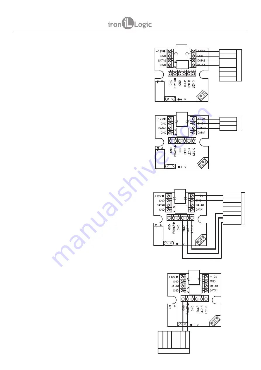
8.1. Via Wiegand protocol
8.2. Via iButton protocol
8.3. Controlling LEDs and sound
8.4. Controlling reader power
Here is an example of how to connect a reader via
Wiegand protocol. The reader is powered from the
adapter. When a code is transmitted (once) by the
adapter, its check bits are verified to decide if
transmission went OK.
The figure below shows an example of how to
connect a reader via iButton protocol. When the
adapter detects the PRESENCE signal from the
reader on iButton bus, the card code is read three
times in a row by “Read ROM” (0x33) command. If all
three reading results are the same, the code is
deemed to be successfully acquired.
If corresponding signals are connected to the
adapter (as per the Figure below), it becomes
possible to manage the reader audial and visual
indication by COM port commands (as per p.4
above).
All indication control signals have 5 V level.
When reader power is connected to POWER
terminal, it becomes possible to turn it on and off by
the COM port commands. (as per p.4 above).
Please remember that maximum total current of all
12 V devices, including those connected to POWER
terminal, cannot exceed 150 mA.
+12
LED G
BEEP
LED R
DATA 1
GND
DATA 0
5
MATRIX-II EH
+12
GND
DATA 0
5
MATRIX-II
5
+12
LED G
BEEP
LED R
DATA 1
GND
DATA 0
MATRIX-II EH
+12
LEDG
BEEP
LEDR
DA
TA
1
GND
DA
TA
0
5
MATRIX-II EH
page 6
Z-2 BASE
www.ironlogic.me


