background image

IPU 40151 Issue 1 


                              4 of 16 

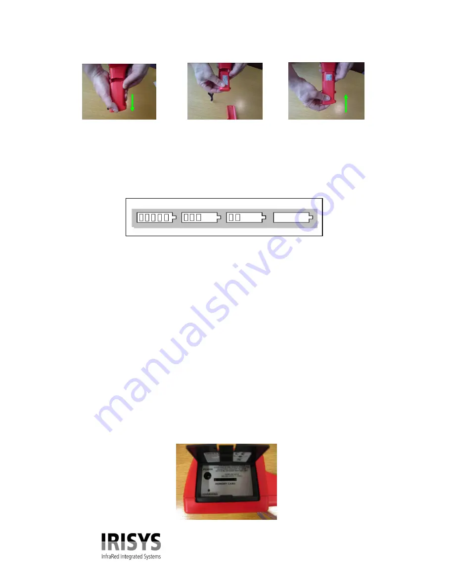
Figure 2.

 Inserting the Rechargeable Battery. 


Remove Battery Cover                Insert Battery                            Replace Battery Cover  

1.5 Battery Recharge Time.


The rechargeable battery will power the IRI 1020 thermal imager for approximately 6 hours. 
The battery indicator appears on the screen when the imager is switched on. It has the following four 
stages and each stage corresponds to approximately two hours of operation as seen in figure 3. 


Figure 3. 

Battery Indicator Levels

.


CAUTION:  If the IRI 1020’s battery indicator flashes, the battery power is running low and it needs 

to be charged or replaced within 10 minutes.  

1.6 Using AC Mains Power. 

 
1.


Make sure the thermal imager is turned off. 

2.


Connect the provided 12V power supply into the socket on the side of the IRI 1020 imager as 
seen in figure 4.


3.


Attach the appropriate supplied regional adapter to the power supply. 

4.


Plug the power supply into a mains socket.  

5.


Switch on the thermal imager. 


CAUTION: When using AC mains, use only the power supply included with the IRI 1020.  Using 
other power supplies may damage the IRI 1020 Thermal Imager.


NOTE: 

The mains power supply included with the IRI 1020 is for powering the IRI 1020; it 

will also recharge the batteries.


1.7 Battery Charging. 

 
The IRI 1020’s battery can be charged in the imager by inserting the included 12V power supply into 
the  DC  socket  under  the  door  on  the  side  of  the  IRI  1020  imager,  as  seen  in  figure  4.  It  takes 
approximately 6 hours to fully charge a fully depleted battery if the imager is switched off. Charging 
the battery with the imager switched on takes longer. 

Figure 4. 

Connecting the Mains AC Power Supply.


6hrs 

4hrs 

2hrs 

0hrs 


Содержание IRI 1020

Страница 1: ...ocedures other than those specified in this document may result in hazardous laser radiation exposure InfraRed Integrated Systems Ltd Park Circle Tithe Barn Way Swan Valley Northampton NN4 9BG United...

Страница 2: ...TTONS 8 3 0 IMAGE ADJUSTMENT 9 4 0 USER SETTINGS 9 5 0 USING THE LASER POINTER 10 6 0 THERMAL IMAGE TRANSFER FROM IRI 1020 TO A PC 10 7 0 INSTALLING SOFTWARE ON A PC 11 7 1 OPERATING IRI 1020 IMAGER S...

Страница 3: ...as seen in figure 1 inspect all the items If any item is damaged or missing notify your dealer immediately Figure 1 Imager toolbox 1 3 Powering the IRI 1020 The IRI 1020 Thermal Imager operates from e...

Страница 4: ...ly into the socket on the side of the IRI 1020 imager as seen in figure 4 3 Attach the appropriate supplied regional adapter to the power supply 4 Plug the power supply into a mains socket 5 Switch on...

Страница 5: ...tment power button and the door to the SD card slot Figure 5 The IRI 1020 Hardware Safety notice The laser used in this device is designated Class 2 Under no circumstances should personnel look straig...

Страница 6: ...fore some of the IR picture will have come from the surrounding background The average background temperature must therefore also be entered into the camera Measurement accuracy falls at low emissivit...

Страница 7: ...any time will restore a usable picture Powering the unit off and on again will restore all factory settings Over and under range values are indicated by red or blue coloured numbers these readings ex...

Страница 8: ...ged by use of the up down left and right directional arrow keys Palette The user can select from three options The palettes are Red Blue Green Blue or Greyscale and are selected by toggling the up dow...

Страница 9: ...his button toggles between auto and manual mode In auto mode the imager continually adjusts the level and span to achieve the optimum image In manual mode it is possible to manually control the level...

Страница 10: ...Figure 12 Inserting the SD card 4 Insert the USB connector of the SD card reader into a USB port on the PC using the extender USB cable if required 5 Follow the card reader s installation instruction...

Страница 11: ...but it is advisable to leave it as the default The installation will also put a Shortcut Icon onto your PCs desktop to allow quick and easy start up of the software 7 1 Operating IRI 1020 Imager Softw...

Страница 12: ...present the upper and lower values of temperature from black cold to white hot 7 4 Thermal Imager Tool Bar Figure 14 Tool bar Save About Edit Colour Map Single Auto Gain Edit Emissivity Toggle Control...

Страница 13: ...ng windows and allows the user to control how they are displayed The options available are Cascade Cascades all open images Tile Displays all open images simultaneously Arrange Icons Arranges the Icon...

Страница 14: ...sitioned chopper blade 9 2 Emissivity Lookup Table Below is a list of approximate emissivity values for a range of materials for making more accurate temperature measurements NOTE Emissivity values of...

Страница 15: ...e complete the details below and send it back to IRISYS at the address on the front page of this manual Name Company Name and address Contact Details IRI 1020 Thermal Imager Serial number This can be...

Отзывы: