background image


                                 General Guidance 


16 

W

ATER CONNECTION


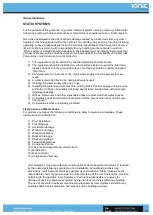
This section deals with the procedure and recommendations for connecting a suitable water 
supply to the Zero™.


Connection 

Follow the guidance on this page and connect a suitable water supply to the connection 
marked ‘Water Connection” and open supply fully.


Suitable Water Supply 

A suitable water supply means water drawn from the mains potable water supply with a 
minimum delivery pressure of 40psi for machines with boosted fill and a minimum delivery 
pressure of 65psi for machines without the boosted fill option.  
 
As well as water pressure, the flow rate of the water supply is an equally important factor. The 
chosen water supply needs to flow a sufficient volume of water to satisfy the machines needs. 
To ascertain the flow rate simply count the number of litres on open flow that is produced in 1 
minute from the chosen water supply (ltrs per min). For example, a machine that is capable of 
producing 5 litres of pure water per minute requires a minimum flow of 10 litres per minute 
from the mains water supply. This is because up to 5 litres per minute is rejected by the 
machine carrying impurities to drain.  
 
A machine capable of producing more than 5 litres of pure water per minute shall require a 
flow rate of at least double its design capability. Where mains water pressure/flow is low the 
use of a break tank will avoid cavitation in the water supply. The size of the break tank will 
depend upon the volume of pure water required and the speed at which it can be refilled. 
Sufficient pressure and flow are both relevant for the machine to perform to its design 
specification.


Unsuitable Water Supply 

In addition to low pressure and low flow, unsuitable water supplies include lakes, reservoirs, 
and rivers, bore holes, and seawater.


Recommendations 

1)  In the case of static machines water connection should be by means of a permanent hard 

piped connection. 


2)  In the case of mobile/vehicle mounted/portable machines a flexible hosepipe connection 

will be suitable.


3)  In all cases the machine should be sited as close to the water supply so that the 

connecting hose can be kept as short as possible. Hoses of 13mm or 1/2inch are suitable 
however hoses of 22mm or 3/4 inch are more desirable especially when the machine is 
sited further away from the water supply.


4)  Care should be taken to ensure that accidental disconnection from the water supply does 

not occur. Beware of vehicles stopping on hoses, poor connections, and disconnection by 
third parties, flattening of hoses during hot weather, kinking of hoses. Take precautions 
such as placing hoses in the shade, protecting hoses from compression by vehicles, 
placing “do not disconnect” signs at mains water connections.


5)  Avoid dirt ingress and flush hoses prior to connection.


6)  Replace damaged or leaking hoses and connections. 

Содержание Zero PPB

Страница 1: ...1 Operators Manual...

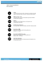
Страница 2: ...bserve for correct operation Electrical Hazard Electrical equipment that is likely to cause serious injury or loss of life CO2 Hazard CO2 Hazard that is likely to cause serious injury or loss of life...

Страница 3: ...tems In 1997 Ionic Systems Ltd introduced the very first vehicle mounted waterfed pole system known as the Reach Wash system Since then Ionic Systems has continued to lead the field with its proven de...

Страница 4: ...ill be different to the summer Ionic Systems is not responsible for your local water supply we have no control over its quality delivery pressure or flow rate Further we have no control over how you u...

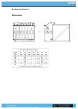
Страница 5: ...Zero Weights Dimensions 5 Dimensions...

Страница 6: ...kg 1225 1242 kg 900 Ltr 200 212kg 1112 1129 kg 800 Ltr 195 212kg 1015 1032 kg 700 Ltr 190 207kg 910 927 kg 600 Ltr 185 202kg 810 827 kg 500 Ltr 180 197kg 705 722 kg 400 Ltr 169 186kg 594 511kg 300 Ltr...

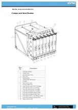
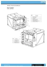
Страница 7: ...Machine Component Identification 7 Component Identification...

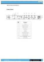
Страница 8: ...Machine Component Identification 8 Control Panel...

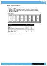
Страница 9: ...pon the specification up to five fuses may be installed The position application and value are depicted in the table below Fuse Box Diagram Fuse box positions 6 8 are not used Function Amps Position S...

Страница 10: ...Machine Component Identification 10 Zero System Filters Removed...

Страница 11: ...rough NGDI filter 0PPB Machines only 10 Delivery Pumps 12v Pure Water delivery pumps 11 A B Incoming and outgoing water connections The system has optional water connections for both left right hand d...

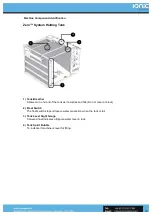
Страница 12: ...out of the tank as it empties and fills Do not cover or block 2 Float Switch The float switch stops ultrapure water production when the tank is full 3 Tank Level Sight Gauge Coloured float indicates...

Страница 13: ...Machine Component Identification 13 Filter Identification Zero PPB System...

Страница 14: ...e Softener Exchanges Calcium and Magnesium ions for Sodium ions Protects the RO membrane RO Filter Reverse Osmosis A semi permeable membrane that filters out 95 98 of dissolved solids De ionisation PP...

Страница 15: ...ater conditions usage and care in routine operation and maintenance Information printed on filter ID discs and in the table below provides estimates about likely filter replacement frequencies Filter...

Страница 16: ...ter pressure flow is low the use of a break tank will avoid cavitation in the water supply The size of the break tank will depend upon the volume of pure water required and the speed at which it can b...

Страница 17: ...s the reject water will fail to flow rejected dissolved solids to drain Temperature has a major effect on pure water production Industry standards for pure water production through an RO membrane are...

Страница 18: ...of a permanent hard wired fused connection 2 In the case of mobile vehicle mounted portable machines a flexible cable connection will be suitable It is highly recommended that an RCD is used at the e...

Страница 19: ...er treatment machine holding tanks transfer pumps and pipe work within the confines of a suitably designed and installed bunded area with adequate drainage capability 7 Offices storerooms and other vu...

Страница 20: ...EEDED DO NOT TO EXCEED THE MAXIMUM PRESSURE TEMPERATURE RANGES WARNING LABELS Like many other cleaning machines Ionic Systems machines with mains powered pumps have no Run Dry protection In the field...

Страница 21: ...salt the second benefit is realised Salt crystals form quickly upon other impurities in water by swelling their physical size they are more easily removed by the RO filter leading to improved RO perf...

Страница 22: ...ny servicing or repairs other than routine filter replacement please refer to Ionic Systems Ltd or an approved agent of Ionic Systems Ltd Step 1 Connect a suitable water supply to the mains water IN c...

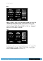
Страница 23: ...to complete At this stage the machine is in open flow and rejected water will be observed flowing to drain Stage 2 After four minutes the SYSTEM PURGING light will extinguish and the SYSTEM FLUSHINGIN...

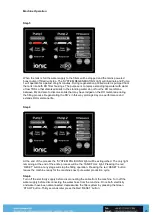
Страница 24: ...lter When the holding tank is full a float switch triggers the end of pure water production The mains water supply will be shut off at the machine the boost pump will stop and the UV 03 lamp will exti...

Страница 25: ...process Regenerating the RO s in this way prolongs day one performance and extends RO membrane life Step 6 At the end of the process the SYSTEM POLISHING light will be extinguished The only light rema...

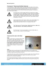
Страница 26: ...om either the vehicles fuel tank or an ancillary remote tank The Thermopure must only be operated in a well ventilated area as carbon monoxide is present in the exhaust gas Operational Procedure Hot W...

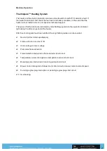
Страница 27: ...after run period of the heater After five short signals have been emitted the long flashing pulses can be counted x1 No start After 2 start up attempts x2 Flame extinction recurrent 5 x3 Under voltage...

Страница 28: ...e left Pump 1 is the hot pump on a Thermopure system and the right pump 2 is always a cold delivery pump On a non Thermopure system they are both cold 1 2 Pump No1 is connected to the upper port on th...

Страница 29: ...Procedures 29 Step 1 Depress the Pump on off 1 for the desired pump The Pump Active light will illuminate 2 Step 2 Select the desired volume for delivery using the or The normal operating volume is l...

Страница 30: ...off If this happens simply depress the Pump On Off 2 and pump will operate once more at the last volume setting On some models pump remote control is fitted This feature means that pumps can be opera...

Страница 31: ...r after periods of exhaustive discharging of the battery it may be necessary to perform a recondition charge This is a setting on the mains charger that can be selected by 3 presses of the mode button...

Страница 32: ...rocedures Filter Replacement 32 Filter Cartridge Replacement 1 Filter Snap Ring 2 Filter Top Cap 3 Filter O ring Seal 4 RO Filter 5 RO Filter Housing NB Snap Rings and O Rings must be replaced every t...

Страница 33: ...c key ring tool to push down on the retaining ring 1 in the filter housing cap then pull the fitting 2 upwards and out of the filter cap 3 Step 2 Move the pipe and fitting clear of the filter cap Step...

Страница 34: ...e is insufficient headroom then it will be necessary to use the key ring tool to remove the pipe from the bottom fitting in the filter housing so that the filter housing can be completely removed from...

Страница 35: ...ined in the top of the filter canister this must also be removed Step 8 With the O ring removed the Filter element can be simply withdrawn by hand and the replacement inserted in its place in this cas...

Страница 36: ...y When it is fully home the groove for the retaining snap ring will be visible Step 12 Insert the pointed end of the snap ring into the groove first With the snap ring located in the grove push it in...

Страница 37: ...e steps below detail the simple the procedure Step 1 After removing the filter housing from the machine insert the orange hose adaptor to the bottom connection on some machines ie Quattro X5 it is pos...

Страница 38: ...mproved RO pre treatment additional water softening One RO maintenance procedure that is commonly over looked in reducing RO cleaning frequency is the use of RO permeate water for flushing foulants fr...

Страница 39: ...approx 2 seconds the charger activates the chosen mode The select mode is saved in the chargers memory and remains even when the charger is switched off Mode Normal 14 4v Normal setting for wet batte...

Страница 40: ...he mode selected will be indicated by the LED s position Battery Information Batteries are only fitted to vehicle mounted systems The battery should never be completely discharged through exhaustive u...

Страница 41: ...bio film thereby prolonging filter life IN ORDER TO PRESERVE THE BENEFITS OF UV 03 STERILISATION THE UV LAMP MUST BE REPLACED EVERY 12 MONTHS UV LAMP REPLACEMENT DISCONNECT MAINS ELECTRICITY BEFORE P...

Страница 42: ...of the UV housing This allows the housing to be unscrewed without twisting the power cables Step 2 Unscrew the end caps at each end of the UV unit Some water inside the housing may escape so it is ad...

Страница 43: ...dures 43 Step 3 Unclip the white plastic connector from each end of the UV lamp Step 4 The UV lamp may now be withdrawn from the housing and replaced Step 5 Installing the new lamp is a reversal of th...

Страница 44: ...ould be replaced at 6 month intervals Putting the machine back into service at the end of storage creates a good opportunity to replace the filter element Carbon Filter The Carbon Filter also traps or...

Страница 45: ...ion remove the snap ring but leave the filter cap in place DO NOT EXPOSE TO FREEZING CONDITIONS Replace the snap ring prior to putting the machine back into service UV O3 To protect against any risk o...

Страница 46: ...it comes across If sufficient pure water is applied all impurities can be flushed away and the remaining mineral free water will dry leaving a clean sterile and spot free finish Window frames can har...

Страница 47: ...ew staff become experienced using short poles before moving up to poles that extend above 10 m Safety in Window Cleaning Scope For the purpose of this guidance the term waterfed pole is defined as a t...

Страница 48: ...and window cleaners need to understand that window cleaners will continue to suffer regular accidents unless a different approach is taken In recent years many window cleaners have adopted the use of...

Страница 49: ...urify water if not replaced at specified intervals filters may become a fertile breeding ground for Legionella bacteria Water temperature is a particularly important factor in the survival of and mult...

Страница 50: ...lkway The design manufacture and instillation of water treatment systems fitted to vehicles should conform to the requirements of The Road Vehicle Construction and Use of Regulations and BS 12195 Load...

Страница 51: ...cally these may include Instruction in the need for the operator to be vigilant with regard to the surroundings Providing adequate PPE and or roof edge protection Giving consideration to the day and t...

Страница 52: ...th battery life are excluded from the warranty 4 12volt pumps are warranted for a period of 3 months only 5 When fitted Stainless Steel filter housings carry a 5 year warranty 6 When fitted mains powe...

Страница 53: ...merchant ability and fitness for a particular purpose Ionic Systems Ltd shall not be responsible for any incidental or consequential damages including travel expense telephone charges loss of income...

Страница 54: ...e as well as to guard against the possibility of harmful Bacteria developing within the system Your Resonsibility Presenting The Reach Wash system for its annual service is the customers responsibilit...

Отзывы: