background image

38

Parameter 1 & Interface Display

Parameter 2 Description

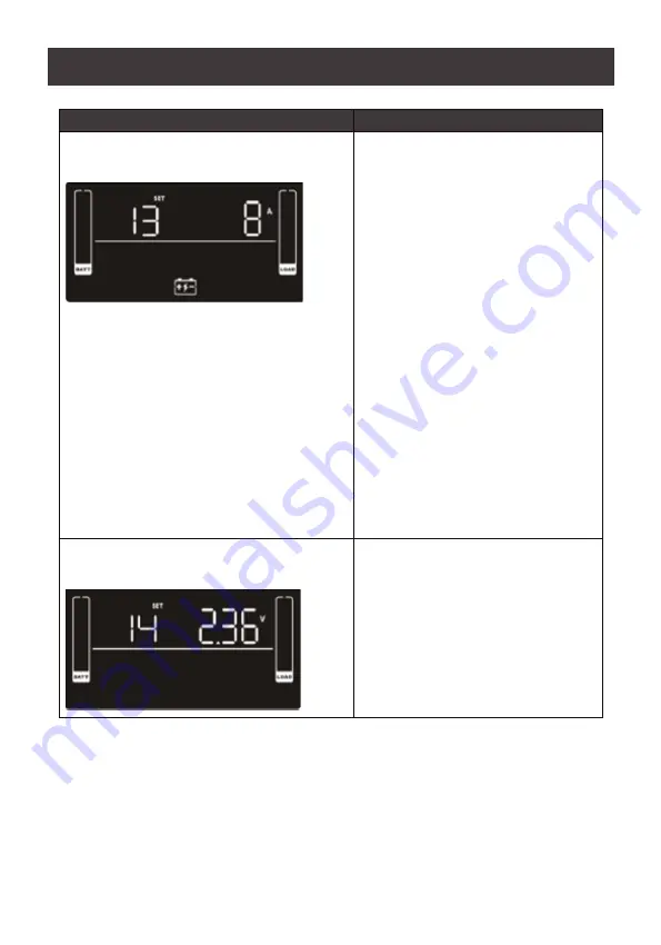
Maximum Charger Current Setting

Display: 13

Parameter 2: Charger Maximum 
Current.

For low voltage model with 
24/36/48VDC

1/2/4/6/8: Set maximum charger current 
to 1/2/4/6/8 Ampere (Default: 2A)

For low voltage and high voltage model 
with 72/96DC

1/2/4/6/8:

 Set maximum charger current 

to 1/2/3/6/8 Ampere (Default: 2A)

Note: 

Please set the appropriate charger 

current based on battery capacity used. 
The recommended charging current 
is 0.1C – 0.3C of battery capacity as 
following table for reference

Warning: 

Setting the current too high 

may cause damage to the device
For the recommended charger current, 
please refer to 

Suggested Battery 

Charger Current

Charger Boost Voltage Setting

Display: 14

Parameter 2: Charger Boost Voltage
2.25 – 2.40: 

Setting the charger boost 

voltage from 2.25V/cell to 2.4V/cell 
(Default: 2.36V/cell)

Содержание GBB1000N

Страница 1: ...www iogear com User Manual IOGEAR Professional Online UPS GBB1000N GBB1500N GBB2000N GBB3000N PART NO M1630 M1631 M1632 M1633 ...

Страница 2: ......

Страница 3: ...nal Battery 21 Installation 23 External Battery 24 General Operations 26 Turning On the UPS 26 EPO Function 26 Initial Software 26 LCD Button Operations 27 Button Operation 27 Audible Alarm 30 LCD Display Wording Index 31 UPS Setting 32 Suggested Battery Charger Current 41 Operating Mode Description 42 Faults Reference Code 43 Warning Indicator 44 Specifications 45 Troubleshooting 47 EMC Informati...

Страница 4: ...d for 100 110 115 120 127 VAC models main cable e g the main cable of your computer to connect the UPS system to the building wiring outlet shockproof outlet Please use only VDE tested CE marked or UL marked for 100 110 115 120 127 VAC models power cables to connect the loads to the UPS system When installing the equipment ensure that the sum of the leakage current of the UPS and the connected dev...

Страница 5: ...ease take the precautionary measure specified below and any other measures necessary when working with batteries Remove watches rings or other metal objects Use tolls with insulated handles Wear rubber gloves and boots Do not lay tools or metal parts on top of batteries Disconnect charging source and load prior to installing or maintaining the battery Remove battery grounds during installation and...

Страница 6: ...kely to cause harmful interference in which case the user will be required to correct the interference at his own expense WARNING Changes or modifications not expressly approved by the party responsible for compliance could void the user s authority to operate the equipment Conventions This manual uses the following conventions Monospaced Indicates text that you should key in Indicates keys you sh...

Страница 7: ...e Rated Description Model Name 1000VA 2B 2 2x9AH 4 pcs batteries in total GBP24V18AH 1500VA 3B 2 3x9AH 6 pcs batteries in total GBP36V18AH 2000VA 4B 2 4x9AH 8 pcs batteries in total GBP48V18AH 3000VA 6B 2 6x9AH 12 pcs batteries in total GBP72V18AH ...

Страница 8: ...onnected equipment may be left on while replacing a new battery ECO mode for energy saving Offers up to 97 efficiency to cut energy usage and cost UPS power application via static bypass timely returning to online double conversion when the need arises Provides more voltage cut off protection and surge immunity by Metal Oxide Varistor MOV an electronic component that protects equipment from voltag...

Страница 9: ...n 4 Off Enter Button Push this button to turn off the LCD 5 Removable Front Panel Model GBB1000N GBB1000SN GBB1500N GBB2000N GBB2000SN 20A GBB3000N 40A The UPS is composed of mains input EMI RFI filters rectifier PFC inverter battery charger DC to DC converter battery dynamic bypass and UPS output To reduce the risk of fire connect only to a circuit provided with A maximum branch circuit overcurre...

Страница 10: ...10 UPS Front View GBB1000N GBB1500N GBB2000N GBB3000N 1 4 7 5 8 9 1 4 7 5 8 9 1 4 7 5 9 1K 1 5K to GBB1000N GBB1500N GBB2000N GBB3000N 6 3 2 10 6 3 2 10 6 6 10 2 8 11 3 ...

Страница 11: ... Communication Port For scheduled UPS shutdown start up and status monitoring 7 SNMP Intelligent Slot The UPS is equipped with intelligent slot perfect for SNMP When installing SNMP in the UPS it will provide advanced communication and monitoring options 8 Emergency Power Off Function Connector EPO Enables an emergency UPS Power Off from a remote location 9 External Battery Connection Port This po...

Страница 12: ...nd the rack mounting kit installs the UPS to onto the rack To mount the UPS please follow below steps 1 Make sure that the rail slide kit includes all of the components shown in the diagram below The components include 2 x slide rails 1 for each side indicated by L and R in the diagram below 6 x M6 nuts 4 x fixing studs 8 x M6 screws 2 Insert the 4 fixing studs two screw holes are available on bot...

Страница 13: ...ng studs into the columns holes on the same level This step serves to hold the slider rail in place for the latter steps 4 Screw a M6 screw into each of the bottom holes to fix the rail slider in place for both ends of the rail and for both rail sliders a total of 4 M6 screws will be used here M6 Screw Bottom hole ...

Страница 14: ...t the M6 nuts onto the support columns as shown below 6 Attach the mounting kit onto the UPS by screwing M4 screws into the mounting kit screw holes and the UPS as shown below M6 Nuts M6 Nuts M4 Screws M4 Screws ...

Страница 15: ...15 7 Fit the UPS onto the rack rails and stabilize the mounting kit M6 screws onto the rack as shown below M6 Screws M6 Screws ...

Страница 16: ...e to vertically mount the unit on a desktop 1 Position the mounting feet as shown below Level and connect the hooks of the mounting feet 2 Stabilize the mounting feet by screwing M4 screw from the hooks to the mounting feet Completed mounting feet ...

Страница 17: ...17 3 Place the unit on the mounting feet 4 Remove the front panel Pull to loosen the hooks and withdraw the panel ...

Страница 18: ...18 5 Turn the LCD panel so that the buttons are below the LCD screen 6 Replace the front panel back to the unit ...

Страница 19: ...t Two mounting feet and two foot extenders are shown below 1 Position the foot extenders as shown below Level and connect the extenders to the bottom of the mounting feet as indicated by the arrow Make sure the hooks are properly secured into the mounting feet 2 Stabilize the foot extenders by screwing M4 screws from the hooks to the mounting feet ...

Страница 20: ... the mounting feet as shown below Level and connect the hooks of the mounting feet 4 Stabilize the mounting feet by screwing M4 screws from the hooks to the mounting feet Completed mounting feet will look like below ...

Страница 21: ...tery For safety the internal battery of the unit is disconnected by default Please follow steps below to reconnect the battery wires Note It is recommended that no power is connected during this time to prevent electric shock 1 Remove the front panel Pull to loosen the hooks and withdraw the panel ...

Страница 22: ...22 2 Connect the power connectors of the battery and the unit together 3 Replace the front panel back to the unit ...

Страница 23: ...ction 4 Optional Connect a modem phone fax source using a corresponding cable into the surge protected IN outlet Connect an equipment you wish to have surge protection for to the OUT outlet using another modem fax phone cable 5 Optional Connect the USB Type B end of the included USB cable to the unit and the USB Type A end to a USB port on your PC 6 Optional Connect the included RS 232 cable betwe...

Страница 24: ...he positive pole of the external battery connector to the UPS to prevent damage The required specification of breaker Voltage 1 25 battery voltage set Current 50A Please choose battery size and connected numbers according to backup time requirement and UPS specifications To extend battery lifecycle we highly recommend using them in temperature range of 15 C to 25 C 59 F to 77 F Please follow below...

Страница 25: ... battery pack to the first battery connection port of the second battery pack 4 Plug the cable connector into the External Battery Connection Port of the unit and the battery pack s 5 Stabilize the connectors to the unit and the battery pack s using screws An example is shown below 6 On the front side of the unit reconnect the battery connector and reattach the front cover ...

Страница 26: ...se refer to EPO Logic Setting for details Initial Software For optimal computer system protection install the UPS monitoring software to fully configure UPS shutdown Use the included RS 232 or USB communication cable to connect the RS 232 USB port of the UPS and RS 232 USB port of the PC Then please follow below steps to install monitoring software 1 Insert the included installation CD into CD ROM...

Страница 27: ... for 2 sec onds to enter UPS self testing while in AC mode ECO mode or Converter Mode OFF Enter Button Turning the UPS Off Press and hold Off Enter button for at least 2 seconds UPS will be in standby mode under normal power or transfer to Bypass Mode if the Bypass setting is enabled Confirm Selection Key Press this button to confirm selection in UPS setting mode Select Button Switch LCD message P...

Страница 28: ...ration Indicates that the UPS Alarm is disabled Button Function ON Mute Button Select Button Switch to Bypass Mode When the main power is normal press ON Mute and Select buttons simultaneously for 3 seconds Then the UPS will enter Bypass Mode This action will be inef fective when the input voltage is out of acceptable range Exit Setting Mode or Return to Upper Menu When working in Setting Mode pre...

Страница 29: ...es the load level by 0 24 25 49 50 74 and 75 100 Indicates overload Programmable Outlets Information Indicates the programmable management outlets are working Mode Operation Information Indicates the UPS connects to the mains Indicates the battery is working Indicates charging status Indicates the bypass circuit is working Indicates the ECO mode is enabled Indicates the AC to DC Circuit is working...

Страница 30: ...y level by 0 24 25 49 50 74 and 75 100 Indicates low battery Mode Alarm Pattern Battery Mode Beep once every 5 seconds Low Battery Beep once every 2 seconds Overload Beep once every second Fault Beeps continuously Bypass Mode Beep every 10 seconds Audible Alarm ...

Страница 31: ...ted Autonomy Time RAT Running Autonomy Time SD Shutdown OK OK ON ON BL Battery Low OL Overload OI Over Input Current NC Battery No Connect OC Overcharge SF Site Wiring Fault EP EPO TP Temperature CH Charger BF Battery Fault BV Bypass Out Range FU Bypass Frequency Unstable BR Battery Replace EE page 29 30 EEPROM error LCD Display Wording Index ...

Страница 32: ...The number shown here is the option or value for the settings determined in parameter 1 Parameter Settings Parameter 1 Interface Display Parameter 2 Description Output Voltage Setting Display 01 Parameter 2 Output Voltage 100 100vac output voltage 110 110vac output voltage 115 115vac output voltage 120 120vac output voltage Default 125 125vac output voltage 127 127vac output voltage 127 is not app...

Страница 33: ... Frequency Setting Display 03 Parameter 2 Output Frequency You may set the initial frequency on Battery Mode BAT 50 50Hz output frequency BAT 60 60Hz output frequency If converter mode is enabled you may choose the following output frequencies CF 50 50Hz output frequency CF 60 60Hz output frequency Enable Disable ECO Display 04 Parameter 2 Enable or Disable ECO Function You may choose between belo...

Страница 34: ...7 VAC models 127 is not applicable to US voltage the setting range is from 3V to 12V of the nominal voltage Default 6V LLS Low Loss Voltage in ECO Mode in Parameter2 Default 12V For 100 110 115 120 127 VAC models 127 is not applicable to US voltage the setting voltage is from 3V to 12V of the nominal voltage Default 6V Enable Disable Bypass when UPS is off Display 06 Parameter 2 Enable or Disable ...

Страница 35: ...ress the Up or Down key to adjust the values HLS Bypass High Voltage Point For 100 110 115 120 125 127 VAC models 127 is not applicable to US voltage 120 140 Setting the high voltage point from 120Vac to 140Vac Default 132Vac LLS Bypass low voltage Point For 100 110 115 120 125 127 VAC models 127 is not applicable to US voltage 85 115 Setting the low voltage point from 85Vac to 115Vac Default 85Va...

Страница 36: ...om 51Hz to 55Hz Default 53 0Hz For 60Hz output frequency models 61 65Hz Setting the frequency high loss point from 61Hz to 65Hz Default 63 0Hz LLS Bypass low Frequency Point For 50Hz output frequency models 45 49Hz Setting the frequency low loss point from 45Hz to 49Hz Default 47 0Hz For 60Hz output frequency models 55 59Hz Setting the frequency low loss point from 55Hz to 59Hz Default 57 0Hz Enab...

Страница 37: ...Setting Display 11 Parameter 2 Backup time on battery mode for general outlets 0 999 Set the backup time in minutes from 0 999 for general outlets on battery mode DIS Disable the autonomy limitation and the backup time will depend on battery capacity Default Note When setting as 0 the backup time will only be 10 seconds Battery Total AH Setting Display 12 Parameter 2 Battery Total AH of the UPS 7 ...

Страница 38: ...nt to 1 2 3 6 8 Ampere Default 2A Note Please set the appropriate charger current based on battery capacity used The recommended charging current is 0 1C 0 3C of battery capacity as following table for reference Warning Setting the current too high may cause damage to the device For the recommended charger current please refer to Suggested Battery Charger Current Charger Boost Voltage Setting Disp...

Страница 39: ...eter 2 EPO Function Control Logic AO Active Open Default When this is selected it will activate EPO function with Pin 1 and Pin 2 in open status AC Active Close When this is selected it will activate EPO function with Pin 1 and Pin 2 in close status Site Fault Detection Enable Disable Display 17 Parameter 2 Enable Disable Site Fault Detection You May Choose the Following Two Options ENA Site fault...

Страница 40: ... Display HS Parameter 2 Acceptable High voltage point and acceptable low voltage point for input voltage range Press the Up or Down key to adjust the values HLS Input High Voltage Point For 100 110 115 120 125 127 VAC models 127 is not applicable to US voltage 140 145 150 Setting the high voltage point in Parameter 2 Default 150Vac LLS Bypass low voltage point For 100 110 115 120 125 127 VAC model...

Страница 41: ...7 12 7 GBP48V18AH 135 12 8 GBP48V18AH 153 12 9 GBP48V18AH 171 12 10 GBP48V18AH 189 12 AH Suggested Charging Current 1500VA 3B 9 2 1 GBP36V18AH 27 4 2 GBP36V18AH 45 6 3 GBP36V18AH 63 8 4 GBP36V18AH 81 10 5 GBP36V18AH 99 10 6 GBP36V18AH 117 12 7 GBP36V18AH 135 12 8 GBP36V18AH 153 12 9 GBP36V18AH 171 12 10 GBP36V18AH 189 12 AH Suggested Charging Current 3000VA 6B 9 2 1 GBP72V18AH 27 4 2 GBP72V18AH 45...

Страница 42: ... also charge the battery Frequency Converter Mode When the input frequency is within 40Hz and 70Hz the UPS can be set at a constant output frequency of 50Hz or 60Hz The UPS will also charge the battery Battery Mode When the input voltage is beyond the acceptable range or power failure the UPS will provide backup power from the battery Alarm will beep every 5 seconds Bypass Mode When the input volt...

Страница 43: ...be displayed Faults Reference Code Fault Event Fault Code Icon Fault Event Fault Code Icon Bus start fail 01 X Battery voltage too high 27 X Bus over 02 X Battery voltage too low 28 X Bus under 03 X Charger output short 2A X Inverter soft start fail 11 X Over temperature 41 X Inverter Voltage High 12 X Overload 43 Inverter Voltage Low 13 X Charger failure 45 X Inverter Output Short 14 X Over input...

Страница 44: ...able Beeps every 2 seconds Over Temperature Beeps every 2 seconds Charger Failure Beeps every 2 seconds Battery Fault Beeps every 2 seconds UPS will be off to remind users something is wrong with the battery Out of Bypass Voltage Range Beeps every 2 seconds Bypass Frequency Unstable Beeps every 2 seconds Battery Replacement Beeps every 2 seconds EEPROM Error Beeps every 2 seconds Note Site Wiring ...

Страница 45: ...equency Range 40Hz 70Hz Rated input current 9 3A 13 2A 17 6A 26 4A Input Power Factor 0 99 nominal voltage 100 load Cold Start Yes Plug Type NEMA 5 15P NEMA 5 15P NEMA 5 20P NEMA L5 30P Power Cords 6ft Output VA 1000 1500 2000 3000 Watts 1000 1430 1930 2850 On Battery Waveform Sine Wave On Battery Voltage 100 110 115 120 125 127 VAC models 127 is not applicable to US voltage On Battery Frequency 5...

Страница 46: ...Size 12V 9AH 12V 9AH 12V 9AH 12V 9AH Battery Quantity 2 3 4 6 Hot Swappable Yes Typical Recharge Time 3 hours recover to 95 capacity 2A charging current Max charger current 8A Extender Battery Module GBP24V18AH GBP36V18AH GBP48V18AH GBP72V18AH Physical Properties Rack Size 2U Form Factor Rack Tower Dimensions WxHxD mm3 438 x 88 x 410 438 x 88 x 410 438 x 88 x 510 438 x 88 x 630 Weight kg 11 6 14 1...

Страница 47: ...s EPO function is activated Set the circuit in closed position to disable EPO function Icon and and warning code flash on LCD display Alarm beeps every 2 seconds Line and neutral conductors of UPS input are reversed Rotate mains power socket by 180degree and then connect to UPS system Icon and and Warning code Flash on LCD display Alarm beeps every 2 seconds The external or internal battery is inc...

Страница 48: ...n shut down the UPS and restart it Fault code is shown as 49 on LCD display Alarm continuously beeps UPS is over input current Remove excess loads from UPS output Fault code is shown as 43 and icon shown on the LCD display Alarm continuously beeps The UPS shutdown automatically because of the overload at the UPS output Remove excess loads from UPS output and restart it Fault code is shown as 01 02...

Страница 49: ...our dealer Batteries defect Contact your dealer to replace the battery Fault code is shown as 2A on LCD display Alarm continuously beeps The short circuit occurs on the charger output Check if battery wiring of connected external pack is in short circuit status Fault code is shown as 45 on LCD display Alarm continuously beeps The charger does not have output and battery voltage is less than 10V PC...

Страница 50: ...e in which case the user will be required to correct the interference at his own expense FCC Caution Any changes or modifications not expressly approved by the party responsible for compliance could void the user s authority to operate this equipment Warning Operation of this equipment in a residential environment could cause radio interference This device complies with Part 15 of the FCC Rules Op...

Страница 51: ...r more product information 2 Visit www iogear com support for live help and product support IOGEAR www iogear com support support iogear com www iogear com Contact Limited Warranty 2021 IOGEAR Part No M1630 M1631 M1632 M1633 IOGEAR the IOGEAR logo are trademarks or registered trademarks of IOGEAR Microsoft and Windows are registered trademarks of Microsoft Corporation All other brand and product n...

Страница 52: ... 2020 IOGEAR ...

Отзывы: