


6
MSK-101 | Advanced configuration manual v1.5 MAY 2018 | msk-101_advanced-config_en_wo v1.5 | © 2017-2018 Inxpect SpA
MSK-101
Description
MSK-101 is an advanced motion sensor for high
security intrusion detection systems.
Thanks to a proprietary motion detection motor
based on FMCW radar, it can detect intruders while
minimizing false alarms triggered by small animals,
moving objects or environmental conditions. It
signals the presence of intruders through activation
of the dedicated relay outputs and LED on the front of
the sensor.
Thanks to IP66 and IP68 protection grade, it is
suitable for indoor and outdoor installations.
Special features
The sensor calculates the distance and estimates
dimensions of the moving object in real time,
permitting advanced configuration possibilities in
respect to traditional motion sensors. In particular, it
is possible to:
l
set a pre-alarm area at the margins of the
monitored area for activation of deterrent actions
(e.g.: turning on the lights)
l
fine set the tolerance level for animals
l
exclude any moving objects that would generate
continuous false alarms from the monitored area
Main components
Part
Description
A
Perforated housing base for adaptation to the
main junction boxes
IMPORTANT: the base of the
container is, together with the two
fastening screws (not provided), an
integral part of the sensor anti-removal
and anti-tear system.
B
Sensor housing
C
Adjustable support for the sensor with
integrated fastening screws
D
Sensor
Part
Description
E
Caps to cover the fastening screws of the
adjustable support
F
Box-base fastening screw
Note: the container-base fastening screw is
not a part of the sensor anti-removal and
anti-tear system.
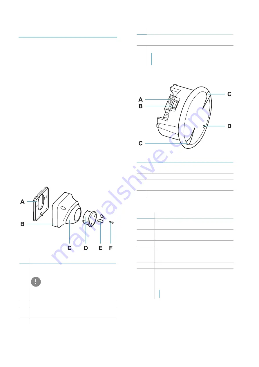
Sensor
Part
Description
A
Terminal block for connecting power supply
and four relays
B
Connector for connecting the dongle
C
Sensor plane indicators (horizontal or
vertical)
D
LED
LED
Status
Meaning
Steady
red
Motion detected in alarm area
Flashing
red
Motion detected in pre-alarm area
Purple
Sensor tampered with, faulty or masked
Flashing
purple
Permanent fault. Contact technical
assistance to repair or replace the
sensor.
Blue
Motion signal processing in progress.
Flashing
blue
Sensor initialization phase in progress.
Requires a free area of approximately 1
m around the sensor and lasts 10-15
seconds.
Note: during the initialization phase, the
masking signal is disabled.
Get to know MSK-101
Содержание MSK-101
Страница 33: ......


