manualshive.com logo in svg
background image

Original instructions

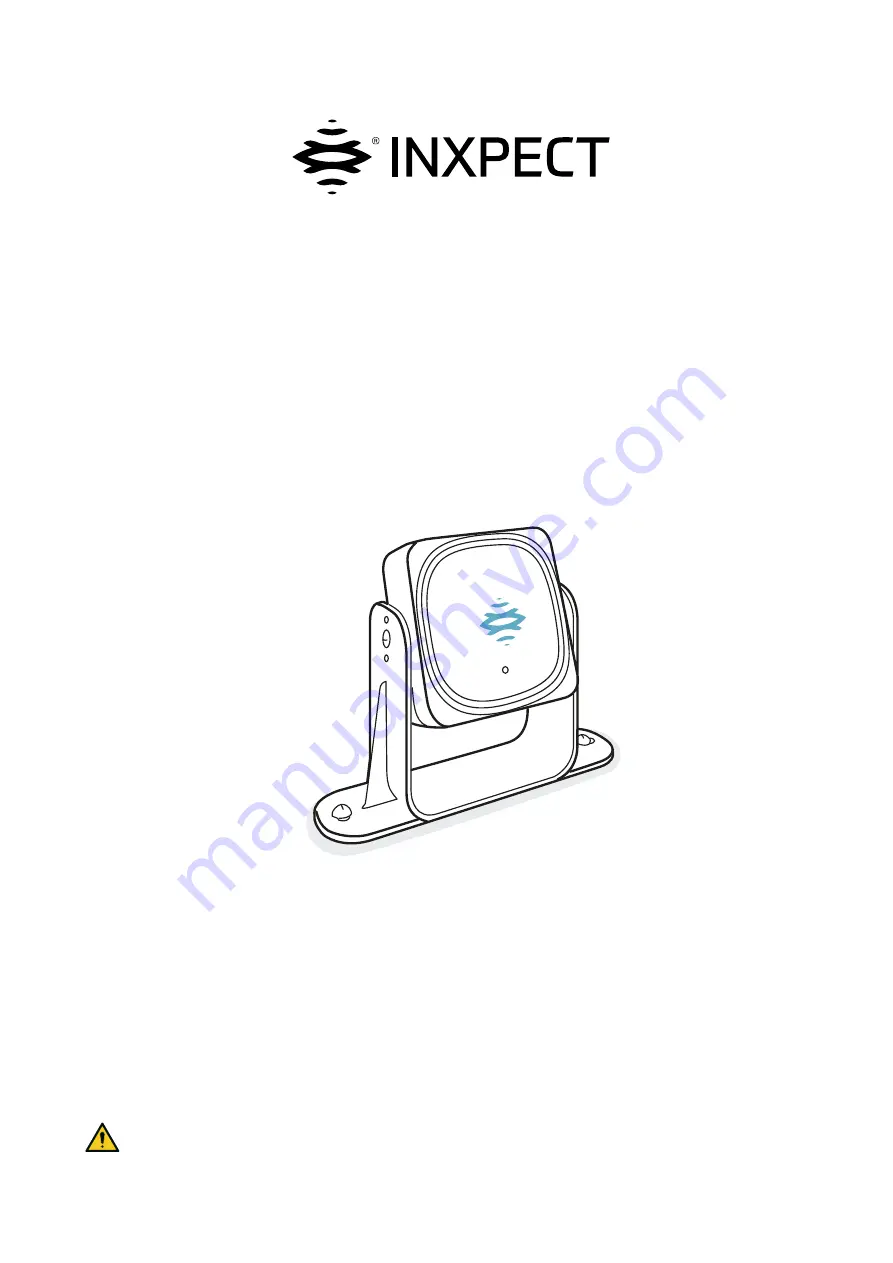
LBK System BUS

Instruction manual

v1.0 - EN

SRE - Safety Radar Equipment

WARNING! Any who uses this system must read the instruction manual to ensure safety. Read
and adhere to the "Safety information" chapter in its entirety before using the system for the first
time.

Содержание LBK System BUS

Страница 1: ...truction manual v1 0 EN SRE Safety Radar Equipment WARNING Any who uses this system must read the instruction manual to ensure safety Read and adhere to the Safety information chapter in its entirety before using the system for the first time ...

Страница 2: ... totally or partially l Transferring the document on websites or other electronic systems l Copying contents without any modification and stating Inxpect SpA as copyright owner Inxpect SpA reserves the right to make modifications or improvements to the relative documentation without prior notice Requests for authorizations additional copies of this manual or technical information about this manual...

Страница 3: ...eter 33 4 10 Anti tampering functions anti masking 34 4 11 Multi controller Synchronization 35 5 Sensor position 37 5 1 Basic concepts 37 5 2 Sensor field of view 38 5 3 Dangerous area calculation 39 5 4 Calculation of position for sensor height 1 m 40 5 5 Calculation of position for sensor height 1 m 45 5 6 Outdoor installations 46 6 Installation and use procedures 48 6 1 Before installation 48 6...

Страница 4: ...cause it is dangerous for people Deactivated output OFF state Output that switches from ON to OFF state Detection distance 1 Depth of the field of view configured for detection field 1 Detection distance 2 Depth of the field of view configured for detection field 2 Detection field 1 Area of the fieldset closer to the sensor In the absence of detection field 2 it corresponds to the whole fieldset D...

Страница 5: ... fields FMCW Frequency Modulated Continuous Wave I Inclination Sensor rotation around the transverse axis The sensor inclination is the angle between the center of the field of view of the sensor and a line parallel to the ground M Machinery The system for which the dangerous area is monitored Monitored area Area that is monitored by the system It is composed of detection field 1 e g used as alarm...

Страница 6: ...ce Service Always enclose the manual when the equipment is sold 1 1 3 Provided documentation Document Code Date Distribution format Instruction manual this manual LBK System BUS_ instructions_en v1 0 SEP 2020 online PDF PDF downloadable from the site www inxpect com industrial tools Instruction manual to interact with Inxpect Safety LBK app_instructions_ en v1 4 JAN 2020 the online help accessible...

Страница 7: ...must be reduced based on risk assessment l Knowledge of the entire machinery safety system and the system on which it is installed Protection system installer l Installs the system l Configures the system l Prints configuration report l Advanced technical knowledge in the electrical and industrial safety fields l Knowledge of the dimensions of the dangerous area of the machinery to be monitored l ...

Страница 8: ...re the system is stored and installed is compatible with the storage and operating temperatures indicated in the technical data of this manual 2 1 6 WARNINGS FOR THE RESTART PREVENTION FUNCTION l The restart prevention function is not guaranteed in blind spots If required by the risk assessment implement adequate safety measures in those areas l Machinery restarting must be enabled only in safe co...

Страница 9: ...U RED Radio equipment and is subject to the following restrictions FR UK en Restrictions in UK In the United Kingdom the national allocation of frequencies does not allow the free use of the whole band 24 24 25 GHz Set the country correctly in the Inxpect Safety application and the authorized band 24 05 24 25 GHz will be automatically selected fr Restrictions en FR En France la répartition nationa...

Страница 10: ...AR Restricciones en Argentina La atribución de las bandas de frecuencia en la República Argentina no permite el uso libre de toda la banda de 24 24 25 GHz Configure correctamente el país en la aplicación Inxpect Safety y la banda autorizada 24 05 24 25 GHz se seleccionará automáticamente 2 3 5 MEXICO en Restrictions in Mexico In Mexico the national allocation of frequencies does not allow the free...

Страница 11: ...BK System BUS is an active protection radar system that monitors the dangerous areas of machinery 3 1 2 Special features Some of the special features of this protection system are the following l immunity to dust and smoke l reduction of undesired alarms caused by the presence of water or processing waste l possibility to configure a second safe detection field e g used as warning area to signal p...

Страница 12: ...ommunication on a Fieldbus interface The Fieldbus interface allows the ISC B01 controller to communicate in real time with the PLC of the machinery in order to do what follows l send information about the system to the PLC e g the position of the detected target l receive information from the PLC to change the configuration dynamically See Fieldbus communication on page 18 3 1 6 Applications LBK S...

Страница 13: ...fety PLC through Fieldbus connection Note only if the controller supports the safety communication on the Fieldbus interface For details see Safety Fieldbus support on page 18 3 2 2 Structure Part Description A I O terminal block B Sensor status LEDs C Network parameter reset button D Output reset button E Micro USB port for connecting the PC and communicating with the Inxpect Safety application F...

Страница 14: ...functions are the following l Stop signal manages a specific signal to force all the safety outputs detection signal 1 and detection signal 2 if present to OFF state l Restart signal manages a specific signal which enables the controller to switch the safety outputs related to all the detection fields that are free of movements to ON state l Muting group N manages a specific signal which allows th...

Страница 15: ...remains in OFF state as long as a movement is detected in the monitored area then it is activated ON state and the ON state lasts as long as the entire monitored area is free of movements and until the Restart Signal is activated on the dedicated input o safe manual restart prevention the dedicated output remains in OFF state as long as a movement is detected in the monitored area then it is activ...

Страница 16: ... Send the motion detection signal to the controller through CAN bus l Signal to the controller through CAN bus the failures or faults detected on the sensor during diagnostics 3 3 2 Structure Part Description A Sensor B Screws for fastening the sensor at a specific inclination C Perforated bracket for installing the sensor on the ground or on the machinery D Status LED E Connectors for connecting ...

Страница 17: ...ough the application and then saved on the controller The available functions according to access type are presented as follows Available functions Access type l Display the system status Dashboard l Display the sensors configuration Configuration l Restore factory default settings if not using Ethernet connection Configuration Settings General l Back up the configuration Configuration Settings Ge...

Страница 18: ...onfiguration functions Admin password required Disconnect Close the connection with the device and allow to connect to another device Change the language 3 5 Fieldbus communication 3 5 1 Safety Fieldbus support The safety communication on the Fieldbus interface is supported from controller firmware version 1 2 0 If the controller firmware version is 1 1 0 the controller can manage the system safet...

Страница 19: ...6 System configuration 3 6 1 System configuration The controller parameters have their own default values that can be modified via the Inxpect Safety application see Parameters on page 74 3 6 2 Dynamic system configuration LBK System BUS allows a real time adjustment of the most important system parameters providing the means to switch dynamically among different preset configurations Via the Inxp...

Страница 20: ...amic configuration four preset configurations see Example 3 below Example 1 The first digital input has been linked to the dynamic configuration Configuration Input 1 Input 2 Dynamic configuration 1 0 Dynamic configuration 2 1 0 signal deactivated 1 signal activated Example 2 The second digital input has been linked to the dynamic configuration Configuration Input 1 Input 2 Dynamic configuration 1...

Страница 21: ...the mounted sensor stops the system cannot restart automatically In fact it is necessary that the operator authorizes the machinery to restart with the new configuration refer to Sensor mounted on fixed machinery below Example The sensor is mounted on a movable machinery to avoid the impact between the moving part and a potential target e g sensor mounted on AGVs cranes wood machines with moving a...

Страница 22: ...ring functions anti masking 34 4 11 Multi controller Synchronization 35 4 1 Sensor functioning principles 4 1 1 Introduction LBK S01 is an FMCW Frequency Modulated Continuous Wave radar device based on a proprietary detection algorithm LBK S01 is also a single target sensor that sends impulses and obtains information analyzing the reflection of the nearest moving target that it encounters Each sen...

Страница 23: ...ducts that fall within the field of view of the sensor 4 2 System category according to EN ISO 13849 4 2 1 System safety degree Both ISC B01 and LBK S01 are classified PLd according to EN ISO 13849 1 and SIL 2 according to IEC EN 62061 According to EN ISO 13849 1 the architectures of the ISC B01 controller and LBK S01 sensor are classified respectively as category 3 equivalent and category 2 Since...

Страница 24: ...ection and restart prevention o Sensor 1 restart prevention Sensor 2 restart prevention l Sensors that monitor the same area must have the same restart timeout l The muting of sensors that monitor the same area must be enabled or disabled at the same time If multiple configurations were stored on the controller each single configuration should comply with the requirements listed above in order to ...

Страница 25: ...ach of its detection fields l Both default o the sensor performs the access detection function when it is in normal operation No alarm status o the sensor performs the restart prevention function when it is in alarm status Alarm status l Always access detection o the sensor always performs the access detection function No alarm status Alarm status l Always restart prevention o the sensor always pe...

Страница 26: ...ld 2 access detection function l Detection field 1 restart prevention function l Detection field 2 restart prevention function 110 l Detection field 1 access detection function l Detection field 2 access detection function l Detection field 1 restart prevention function l Detection field 2 restart prevention function If the motion is detected in the Then the output of detection field 1 And the out...

Страница 27: ...nction l Detection field 2 access prevention function 110 l Detection field 1 access detection function l Detection field 2 access detection function l Detection field 1 restart prevention function l Detection field 2 access prevention function If the motion is detected in the Then the output of detection field 1 And the output of detection field 2 detection field 1 is deactivated and switches to ...

Страница 28: ...tion field 2 access prevention function 110 l Detection field 1 access detection function l Detection field 2 access detection function l Detection field 1 access prevention function l Detection field 2 access prevention function If the motion is detected in the Then the output of detection field 1 And the output of detection field 2 detection field 1 is deactivated and remains in the access preve...

Страница 29: ...afety function access detection Access detection allows what follows When Then no motion is detected in the detection field the safety outputs remain active motion is detected in the detection field l the safety outputs are deactivated l the restart prevention function is activated 4 4 3 Safety function restart prevention The restart prevention function remains active and the safety outputs deacti...

Страница 30: ...breathing movements with normal breathing or a short apnea or the movements necessary for a person to remain in balance in an upright or squatting position The system sensitivity is higher than the sensitivity that characterizes the access detection function For this reason the system reaction to vibrating and moving parts is different The restart prevention allows what follows When Then no motion...

Страница 31: ...body parts within the sensor field of view but the axis of the person s center of gravity is outside that field Only when there are no restrictions does the function ensure that a person is detected when standing up D 4 Functioning principles LBK System BUS Instruction manual v1 0 SEP 2020 LBK System BUS_instructions_en v1 0 2020 Inxpect SpA 31 ...

Страница 32: ... height of less than 30 cm from the ground a minimum distance of 30 cm from the sensor must be guaranteed 4 7 4 Enable the restart prevention function Type Procedure Automatic In the Inxpect Safety application Configuration Settings Sensors set the Restart timeout Manual 1 Connect the machinery restart enable button conveniently see Electrical connections on page 69 2 In the Inxpect Safety applica...

Страница 33: ...parameters that define the characteristics of the signal Note with pulse duration 0 it is sufficient that the input signals are at high logic level 1 to enable muting 4 8 4 Muting status Any output dedicated to the muting status Muting enable feedback signal is activated if at least one of the groups of sensors is in muting NOTICE it is the responsibility of the machinery manufacturer to assess wh...

Страница 34: ...0 1 Masking signal The sensor detects the presence of objects that could obstruct the field of view When the system configuration is saved the sensor memorizes the surrounding environment If the sensor subsequently detects variations in the environment that could influence the field of view it sends a masking signal to the controller Upon reception of a masking signal the controller deactivates th...

Страница 35: ... anti masking function is disabled When the anti masking function is disabled perform the following checks Safety function Schedule Action Access detection function Before each machinery restart Remove any objects that obstruct the field of view of the sensor Reposition the sensor according to the initial installation Restart prevention function Each time the safety outputs are deactivated 4 10 7 ...

Страница 36: ... the Multi controller Synchronization function Note only if this function is available in the Inxpect Safety application 1 In the Inxpect Safety application click Configuration Settings Digital Input Output 2 Associate one of the digital inputs of each ISC B01 controller to Acquisition Trigger 4 Functioning principles ...

Страница 37: ... field of view l depth of the dangerous area and therefore the detection field l the presence of other sensors 5 1 2 Sensor installation height The installation height h is the distance between the center of the sensor and the ground or reference plane of the sensor 5 1 3 Sensor inclination Sensor inclination is the rotation of the sensor around its transverse axis Inclination is defined as the an...

Страница 38: ...as iron and water which reflect the radar signal e g iron shavings water splatters rain It is therefore also suitable for outdoor installations WARNING When the restart prevention function is active all the sensors have a 110 angular coverage regardless of the set angular coverage NOTICE during the configuration phase take this aspect into consideration to avoid generating undesired alarms 5 2 3 A...

Страница 39: ... 1 m To calculate the depth of the dangerous area S for sensors with installation heights less than or equal to 1 m use the following formula Where Variable Description Value Measurement unit K Maximum dangerous area access speed 1600 mm s T Total system stopping time LBK System BUS machinery 0 1 Machinery stopping time calculated in accordance with ISO 13855 2010 standard s Ch Variable that takes...

Страница 40: ... 850 mm Example 1 l Machinery stopping time 0 5 s T 0 1 s 0 5 s 0 6 s S 1600 0 6 850 1810 mm 5 4 Calculation of position for sensor height 1 m 5 4 1 Introduction The formulas for calculating the optimum position of the sensor for sensors with installation heights less than or equal to 1 m are reported as follows WARNING Define the optimum sensor position based on the risk assessment requirements 5...

Страница 41: ...0 x x 2 x x 50 x 3 2 x x 60 x 3 2 x x 70 x 3 2 x x 80 3 3 2 x x 90 3 3 2 x x 100 3 3 2 x x 5 4 3 Legend Element Description Measurement unit GAP Distance between the ground and the field of view of the sensor cm α Sensor inclination degrees h Sensor installation height cm Dalarm Detection distance linear cm DalarmReal Detection distance real cm S1 Start detection distance cm S2 End detection dista...

Страница 42: ...en v1 0 2020 Inxpect SpA 5 4 4 Configuration 1 In this configuration the field of view of the sensor never intersects the ground To guarantee that the sensor also detects access by people crawling respect the following condition 110 field of view 50 field of view 5 Sensor position ...

Страница 43: ...r intersects the ground To guarantee that the sensor also detects the presence of people crawling near the sensor respect the following condition 110 field of view 50 field of view 5 Sensor position LBK System BUS Instruction manual v1 0 SEP 2020 LBK System BUS_instructions_en v1 0 2020 Inxpect SpA 43 ...

Страница 44: ...nsor always intersect the ground To guarantee optimum performance respect the following conditions 110 field of view 50 field of view 5 4 7 Calculate the real detection distance The actual detection distance DalarmReal is the value to be entered in the Configuration page of the Inxpect Safety application DalarmReal indicates the maximum distance between the sensor and the object to be detected 5 S...

Страница 45: ...istance linear cm DalarmReal Detection distance real cm S1 Start detection distance cm S2 End detection distance cm 5 5 3 110 field of view WARNING It is only possible through the validation procedure see Validate the safety functions on page 54 to check if the other configurations respect the performance levels required by the application 5 5 4 50 field of view WARNING It is only possible through...

Страница 46: ...ation position might be exposed to precipitation that can cause undesired alarms it is recommended to take the following precautions l make a cover to protect the sensor from rain hail or snow l position the sensor so that it does not frame the ground where puddles might form 5 6 2 Recommendations for covering the sensor Below are some recommendations for creating and installing a sensor cover l h...

Страница 47: ... are neither liquids nor reflective materials on the floor Note during the restart prevention function or if the sensor has a 110 field of view undesired alarms may occur due to the higher sensitivity of the system 5 6 4 Position not exposed to precipitation If the installation position of the sensor is not exposed to precipitation no special precautions are required 5 Sensor position LBK System B...

Страница 48: ...equired l Microsoft Windows 7 or later l Apple OS X 10 10 or later 6 1 3 Install the Inxpect Safety application Note if the installation fails the dependencies needed by the application may be missing Update your operating system or contact our Technical Support team to receive assistance 1 Download the application from the www inxpect com industrial tools website and install it on the computer 2 ...

Страница 49: ...al 6 In Operational frequency if the system is installed in one of the countries with national restrictions select the restricted bandwidth otherwise select the full bandwidth Note this setting does not have any effect on system performance or safety 6 2 3 Define the area to be monitored WARNING LBK System BUS is disabled during configuration Prepare opportune safety measures in the dangerous area...

Страница 50: ...kit 1 Position the sensor as indicated in the configuration report and fasten the bracket with two tamper proof screws directly onto the floor or another support NOTICE make sure the support does not inhibit machinery commands 2 Loosen the side screws to tilt the sensor 3 Direct the sensor up to the desired inclination see Sensor position on page 37 Note a notch is equal to 10 of inclination 4 Tig...

Страница 51: ...cket with two screws to a machinery support To select installation height see Sensor position on page 37 2 Loosen the side screws 3 Position the sensor parallel to the machinery support 4 Direct the sensor up to the desired inclination see Sensor position on page 37 Note a notch is equal to 10 of inclination 5 Tighten the screws 6 Installation and use procedures LBK System BUS Instruction manual v...

Страница 52: ... sensor without Node ID to the end of the chain or to substitute an existing sensor 1 Start the Inxpect Safety application 2 Click Configuration Settings Node ID Assignment 3 Connect the desired sensor directly to the controller or to the last sensor on the chain 4 Set the DIP switch of the controller based on its position in the chain see Chain examples on the next page Note the maximum length of...

Страница 53: ...tion 1 In the Inxpect Safety application click APPLY CHANGES the sensors will memorize the inclination set and the surrounding environment The application will transfer the configuration to the controller and once transfer is complete it will generate a configuration report 2 Click to save and print the report 3 Ask the authorized person for a signature 6 2 10 Reset the controller Ethernet paramet...

Страница 54: ...articular attention to the side areas of the field of view and the limit areas e g intersection with any side guards see Example of access points below l Access standing as well as crawling l Access moving slowly and quickly 6 3 3 Example of access points Access points for 110 field of view Access points for 50 field of view 6 3 4 Validate the restart prevention function Example 1 Starting conditi...

Страница 55: ...alidate the restart prevention function on the previous page 3 Check that the sensor behaves as expected 4 Check that the distance where the motion is detected is the expected value 6 3 7 Troubleshooting validation If the sensor does not perform as expected see the following table Cause Solution Presence of objects obstructing the field of view If possible remove the object Otherwise implement add...

Страница 56: ...e ID Assignment Function of inputs and outputs Click Configuration Settings Digital Input Output Muting Click Configuration Settings Muting Sensor inclination Loosen the side screws on the sensor and orient the sensors to the desired inclination Sensor number and positioning Click Configuration Sensor position 4 Click APPLY CHANGES 5 Upon conclusion of transfer of the configuration to the controll...

Страница 57: ... not a valid configuration Therefore the system goes into an alarm status The configuration must be validated and if necessary modified through the Inxpect Safety application by clicking APPLY CHANGES For the default values of the parameters see Parameters on page 74 6 5 5 Identify a sensor In Configuration Settings Node ID Assignment or Configuration Sensor position click Identify near the desire...

Страница 58: ...rol in error Check that the sensor is correctly installed and that the area is free of any objects that obstruct the field of view of the sensors 6 flashes Inclination of the sensor different from the installation inclination Check if the sensor has been tampered with or if the side screws or fastening screws are loose Note flashes at 200 ms intervals and then with a 2 s pause 7 1 2 Controller LED...

Страница 59: ... assistance service Note fault signal on the controller steady LED takes priority over a faulty sensor signal For the status of the single sensor check the sensor LED Note S1 is the first from the top 7 1 3 Other problems Problem Cause Remedy Undesired alarms Transit of people or objects in close proximity to the detection field Change the sensors sensitivity Change the configuration on page 56 Ma...

Страница 60: ...SYSTEM SAFETY ALARM 1426 7 2 3 Download the system log 1 Start the Inxpect Safety application 2 Click Settings and then Activity History 3 Click DOWNLOAD LOG 7 2 4 Radar signal errors SIGNAL ERROR Error Meaning HEAD FAULT Radar not functioning HEAD POWER OFF Radar off MASKING Presence of object obstructing the field of view of the radar SIGNAL DYNAMIC Wrong signal dynamic SIGNAL MIN Signal with dy...

Страница 61: ...controller voltage Screen printing Description VIN Power supply voltage 24 V dc V12 Internal supply voltage V12 sensors Sensors power supply voltage VUSB USB port voltage VREF Inputs reference voltage VSNS Error ADC Analog digital converter 7 2 8 Sensor inclination errors ACCELEROMETER ERROR Error Meaning PITCH ANGLE ERROR Sensor inclination with respect to the bracket set through the side screws ...

Страница 62: ...ts are deactivated 7 2 13 Output errors OSSD ERROR Error Meaning BAD MOSFET1 STATUS Error on diagnostic signal of MOS output 1 BAD MOSFET2 STATUS Error on diagnostic signal of MOS output 2 BAD MOSFET3 STATUS Error on diagnostic signal of MOS output 3 BAD MOSFET4 STATUS Error on diagnostic signal of MOS output 4 7 2 14 Flash errors FLASH ERROR A flash error represents an error on the external flash...

Страница 63: ...updates To download any software updates for the application open the website www inxpect com industrial tools 7 4 2 Download firmware updates To download any firmware updates for the controller and the sensors open the website www inxpect com industrial tools 7 4 3 Install firmware updates only if applicable WARNING During firmware update LBK System BUS may not be fully operative Make sure that t...

Страница 64: ...lowing topics 8 1 Technical data 65 8 2 Terminal blocks and connector pin outs 67 8 3 Electrical connections 69 8 4 Parameters 74 8 5 Digital input signals 75 64 LBK System BUS Instruction manual v1 0 SEP 2020 LBK System BUS_instructions_en v1 0 2020 Inxpect SpA ...

Страница 65: ...safety output and 2 Output Signal Switching Devices OSSDs OSSD characteristic l Maximum load resistance 100 K Ω l Minimum load resistance 70 Ω Safety outputs High side outputs with extended protection function l Max current 0 4 A l Max power 12 W The OSSDs provide what follows l ON state from Uv 1V to Uv Uv 24V 4V l OFF state from 0 V to 2 5 V r m s Inputs 2 dual channel type 3 digital inputs with...

Страница 66: ...nded specifications Section 2 x 0 34 mm2 power supply 2 x 0 25 mm2 data line Type Two twisted pairs power supply and data and one drain wire or shield Connectors 5 pole M12 see Connectors M12 CAN bus on page 68 Connectors shall be type 3 raintight Impedance 120 Ω 12 Ω f 1 MHz Shield Shield with twisted wires in tin plated copper To be connected to earth circuit on the power supply terminal block o...

Страница 67: ...V V SNS common reference for all digital inputs mandatory if at least an input is used 6 Digital Out GND common reference for all digital outputs 7 4 Output 4 OSSD4 8 3 Output 3 OSSD3 9 2 Output 2 OSSD2 10 1 Output 1 OSSD1 11 GND common reference for all digital outputs 12 Note the cables used must have a maximum length of 30 m and the operating temperature must be at least 90 C Note use only copp...

Страница 68: ...at least 80 C Note use only copper wires with 18 AWG min and tightening torque of 0 62 Nm 5 5 lbs in 8 2 4 CAN bus terminal block Symbol Description 12 V dc H CAN H L CAN L GND Note the operating temperature of the cables must be at least 80 C 8 2 5 Connectors M12 CAN bus Male connector Female connector Pin Function 1 Shield to be connected to earth circuit power supply terminal block of the contr...

Страница 69: ...on of safety outputs to the machinery control system 8 3 2 Connection of safety outputs to an external safety relay 8 Technical references LBK System BUS Instruction manual v1 0 SEP 2020 LBK System BUS_instructions_en v1 0 2020 Inxpect SpA 69 ...

Страница 70: ...d emergency button opens the contact when pressed Note the cables used for wiring the digital inputs must have a maximum length of 30 m 8 3 4 Connection of restart enable button Note the indicated restart enable button closes the contact when pressed Note the cables used for wiring the digital inputs must have a maximum length of 30 m 8 Technical references ...

Страница 71: ... output one group of sensors Note the cables used for wiring the digital inputs must have a maximum length of 30 m 8 Technical references LBK System BUS Instruction manual v1 0 SEP 2020 LBK System BUS_instructions_en v1 0 2020 Inxpect SpA 71 ...

Страница 72: ...0 SEP 2020 LBK System BUS_instructions_en v1 0 2020 Inxpect SpA 8 3 6 Connection of the muting input and output two groups of sensors Note the cables used for wiring the digital inputs must have a maximum length of 30 m 8 Technical references ...

Страница 73: ...ection 8 3 8 Diagnostic output connection Note the indicated light turns on in the presence of a failure 8 Technical references LBK System BUS Instruction manual v1 0 SEP 2020 LBK System BUS_instructions_en v1 0 2020 Inxpect SpA 73 ...

Страница 74: ...General Operational frequency Full BW Restricted BW Full BW Configuration Sensor position Number of installed sensors 1 6 1 Plane Dim X 2000 mm Dim Y 1000 mm Dim X 20000 mm Dim Y 20000 mm Dim X 8000 mm Dim Y 4000 mm Position for each sensor X 0 mm Y 0 mm X 20000 mm Y 20000 mm X 2000 mm Y 1000 mm Rotation for each sensor 0 360 0 Inclination for each sensor 0 360 0 Sensor installation height for eac...

Страница 75: ...up N Activate dynamic configuration Fieldbus controlled Restart Feedback signal Acquisition Trigger Note only if the Inxpect Safety application supports the functionality Not configured Digital output for each output System diagnostic signal Muting enable feedback signal Detection signal 1 Detection signal 2 Fieldbus controlled Not configured Configuration Settings Muting Group for muting for each...

Страница 76: ...two input channels remains to the low logic status 0 Stop signal CH1 Stop signal CH2 Interchangeable channel Both channels must go to low logic level 0 to set the Detection signal 1 and Detection signal 2 to OFF state Diff Minor than 50 ms If the value is greater than 50 ms the diagnostic alarm starts and the system deactivates the safety outputs Dt Activation delay Minor than 2 ms 8 5 2 Muting wi...

Страница 77: ... Minor than 200 ms 8 5 3 Restart signal Part Description Detection signal 1 Detection signal 2 The Detection signal 1 and Detection signal 2 outputs go to ON state as soon as the last channel has correctly completed the transition 0 1 0 Restart signal CH1 Restart signal CH2 Interchangeable channel Both channels of Restart signal must have a transition of logical level 0 1 0 The time they stay at h...

Страница 78: ...sentative from whom you purchased the product 9 2 Service and warranty 9 2 1 Customer service Inxpect SpA Via Serpente 91 25131 Brescia BS Italy Tel 39 030 5785105 Fax 39 012 3456789 email safety support inxpect com website www inxpect com 9 2 2 How to return the product If necessary complete the request with information about the return on the website www inxpect com industrial rma Then return th...

Страница 79: ......

Страница 80: ...m BUS Instruction manual v1 0 SEP 2020 LBK System BUS_instructions_en v1 0 Copyright 2020 Inxpect SpA Inxpect SpA Via Serpente 91 25131 Brescia BS Italy www inxpect com safety support inxpect com 39 030 5785105 ...

Отзывы: