background image

9

inVENTer

®

 iV12-Smart

®

/iV12-Smart

®

 Corner ventilation system 

 Installation and operating instructions

sysTem oVerVieW

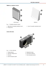
Weather protection hoods

1

3

1

3

2

WSH-Smart

WSH-09

Fig.   5:  Weather protection hoods

1 Base plate of weather protection hood

3 Cover of weather protection hood

2

Fixing screw

Corner lat tube

1

2

5

7

6

3

4

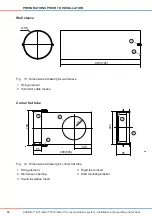
Fig.   6: 

Corner lat tube

1

Fixing element

5

Rigid foam insert

2 Flat tube sliding sleeve

6

Wall sleeve opening

3 Flat tube

7

Wall mounting bracket

4 Sound insulation insert

Содержание iV12-Smart Corner

Страница 1: ...iV12 Smart iV12 Smart Corner ventilation system Installation and operating instructions ...

Страница 2: ...his documentation is an English translation of the original German installation and operating instructions After completion of the installation it should be passed onto the user tenant owner building management etc The contents of this documentation have been checked for compliance with the hardware and software described However discrepancies cannot be ruled out so complete compliance cannot be g...

Страница 3: ...nformation on RAL compliant installation 21 5 4 Creating the wall opening plaster groove 22 5 5 Laying the controller cable 23 5 6 Fitting the wall sleeve 24 5 7 Fitting the weather protection hood 28 5 8 Installing the corner lat tube 34 5 9 Installing the embrasure lattice 37 5 10 Installing the thermal accumulator 39 5 11 Starting the ventilation system 41 5 12 Fitting an inner cover 42 6 opera...

Страница 4: ...ction A keyword above the text indicates the level of risk involved Where several different hazard levels coincide always follow the safety instructions for the highest level Danger Type and source of risk immediate risk of serious personal injury Possible consequences of the risk Action to be taken to avoid the risk Warning Type and source of risk Potential risk of serious personal injury Possibl...

Страница 5: ...system is not suitable for Rooms with corrosive and caustic gases Rooms with extreme dust exposure Drying out buildings Reliable fan operation is only guaranteed in rooms without polluted air The inVENTer ventilation system works with safety extra low voltage Therefore the inVENTer iV14 ventilation unit must not be connected directly to the 230 V power supply it must always be connected via a cont...

Страница 6: ...upply air and exhaust air correspond at least two inVENTer iV12 Smart ventilation units are required One ventilation unit works in supply air mode and the other works in exhaust air mode After 70 seconds the fan changes its rotational direction The inVENTer iV12 Smart ventilation unit is controlled via one of the following inVENTer system controllers ZR8 MZ One ZR10 D The design of the inVENTer iV...

Страница 7: ...otection hood corner 1 Interior plaster 5 Wall sleeve 9 Weather protection hood cover l h embrasure lattice r h 2 Inner cover base plate 6 Fan with felt strip 3 Inner cover holding plate 7 Thermal accumulator 10 Exterior render 4 Inner cover 8 Weather protection hood base plate l h corner lat tube r h 11 Insulation 12 Masonry Wall sleeve 2 1 Fig 2 Wall sleeve 1 Controller cable recess 2 Fixing ele...

Страница 8: ...2 3 5 4 6 Fig 3 Thermal accumulator insert iV12 Smart with fan 1 Thermal accumulator with insulation 4 Felt strip 2 Felt strip 5 Fan mains terminal 3 Reversible fan 6 Controller plug inner covers 3 1 2 4 3 1 2 4 Inner cover V 220x200 Inner cover R D290 Fig 4 Inner covers 1 Panel of inner cover 2 Spacer 3 Base plate of inner cover 4 Dust ilter pollen ilter optional ...

Страница 9: ... 1 3 2 WSH Smart WSH 09 Fig 5 Weather protection hoods 1 Base plate of weather protection hood 3 Cover of weather protection hood 2 Fixing screw Corner lat tube 1 2 5 7 6 3 4 Fig 6 Corner lat tube 1 Fixing element 5 Rigid foam insert 2 Flat tube sliding sleeve 6 Wall sleeve opening 3 Flat tube 7 Wall mounting bracket 4 Sound insulation insert ...

Страница 10: ...ules apply to the functioning of the ventilation units Paired operation of the ventilation units The amount of supply air should correspond to the amount of exhaust air Every ventilation unit that is conveying supply air should be assigned to a different ventilation unit that is simultaneously conveying exhaust air The project can be used to assign the starting order of the ventilation units that ...

Страница 11: ...Flat only or OFF Mode ZR8 Standard only ZR8 Standard and ZR8 Flat controllers differ in terms of airlow at output level zero Use of the ZR8 Flat controller is recommended in rooms where the ventilation unit should not be switched off in order to maintain ventilation to protect against moisture build up features Control of the ventilation unit in three operating modes Ininitely variable adjustment ...

Страница 12: ...only or OFF Mode ZR10 D Standard only The ZR10 D Standard and ZR10 D Flat controllers differ in terms of airlow at output level zero Use of the ZR10D Flatlat controller is recommended in rooms where the ventilation unit should not be switched off in order to maintain ventilation to protect against moisture build up features Control of the ventilation unit in three operating modes Ininitely variabl...

Страница 13: ...epending on your order For each zone the operating mode and output level can be set by means of the 7 day timer or manually The controller can be used both as a base module and in conjunction with additional sensors Through an external interface it can be connected to a potential free loating contact or integrated into an existing home automation system via an analogue input features Intelligent C...

Страница 14: ...g existing buildings Wall thickness1 180 Opening for casing new build Wall thickness1 180 Installation elements Wall sleeve 495 495 160 Wall sleeve 745 745 160 Weather protection hood WSH Smart 44 222 285 Weather protection hood WSH 09 23 88 279 313 Corner 400 lat tube 400 95 224 Corner 500 lat tube 500 95 224 Embrasure lattice 10 104 281 5 Inner cover V 220x200 square 702 224 204 Inner cover R D2...

Страница 15: ...indow frame 3 Position of weather protection hood 6 Bottom edge of embrasure lintel 3 Wall opening iV12 smart with corner connection 155 1 3 4 265 y 285 110 110 1 Ø180 2 5 3 155 1 3 4 365 y 385 110 110 1 Ø180 2 5 3 Corner 4004 lat tube Corner 5004 lat tube Fig 12 Dimensioned drawing for wall opening with corner lat tube 1 Wall opening 4 Outer edge of embrasure ins w plaster 2 Position of corner la...

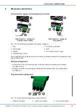
Страница 16: ...Tion Wall sleeve 495 745 160 1 2 Fig 13 Dimensioned drawing for wall sleeve 1 Fixing element 2 Controller cable recess Corner lat tube 120 Ø 162 400 500 55 95 224 239 1 2 4 3 5 Fig 14 Dimensioned drawing for corner lat tube 1 Fixing element 4 Rigid foam insert 2 Wall sleeve opening 5 Wall mounting bracket 3 Sound insulation insert ...
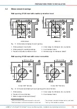
Страница 17: ... Smart WSH 09 Fig 15 Dimensioned drawing for weather protection hoods 1 Base plate of weather protection hood 4 Top drip rail WSH Smart 2 Fixing screws 5 Bottom drip rail WSH Smart 3 Cover of weather protection hood embrasure lattice 10 104 281 5 1 28 1 231 2 2 4 5 3 Fig 16 Dimensioned drawing for embrasure lattice 1 Top drip rail 4 Through hole 2 Louvres 5 Condensate drain 3 Bottom drip rail 281 ...

Страница 18: ...stem Installation and operating instructions PreParaTions Prior To insTallaTion inner cover ø290 70 55 70 224 204 1 2 1 2 Inner cover V 220x200 Inner cover R D290 Fig 17 Dimensioned drawing for inner cover 1 Panel of inner cover 2 Base plate of inner cover ...

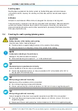
Страница 19: ...roller connection 2 Plug in strip 6 LED 3 Socket 7 Fan mains terminal 3 pole 4 Controller plug 3 pole The running direction of the fan when the controller is started is subject to the alignment of the plug locking screws start up arrangement In exhaust air mode the locking screws of the green plug are pointing up and visible The LED is not on In supply air mode the green plug is rotated and the lo...

Страница 20: ... 1 4 5 With WSH Smart weather protection hood With WSH 09 weather protection hood Fig 20 Preparation set iV12 Smart with weather protection hood 1 Wall sleeve 3 Mounting wedges 5 Weather protection hood WSH Smart WSH 09 2 Protective discs 4 Installation operating instructions 6 2K iiting foam optional 3 6 1 4 2 5 With corner connection Fig 21 Preparation set iV12 Smart with crner connection 1 Wall...

Страница 21: ...L compliant5 and is regulated by standards This procedure must also be applied to inVENTer ventilation units In addition to the load bearing and insulating characteristics of the walls there are also speciied and deined sealing layers Water vapour barrier The water vapour barrier is usually located inside the room and prevents water vapour from penetrating the wall from the living area The water v...

Страница 22: ...Provide protection against falling masonry on the outside of the building Remove objects from immediate vicinity of the outside of the building noTe Condensate collecting in the wall sleeve Damage to the external wall and masonry Incline wall opening at an angle of 1 2 to the external wall TiP Plaster wall groove positioned incorrectly Correct installation of the fan cable is not possible Position...

Страница 23: ... to the external wall Ø 180 1 Mill plaster wall groove 2 Ensure that the plaster wall groove is as near as possible to 45 to the bottom left of the wall opening or Ensure that the plaster wall groove is as near as possible to 45 to the top right of the wall opening 2 Ö Ö Wall opening and plaster wall groove are ready 5 5 laying the controller cable Requirements Wall opening is ready Plaster or wal...

Страница 24: ...m the wall sleeve on the outside depends on the cover to the exterior Requirements Controller cable in place Preparation set is available Determine precise wall thickness Add thickness of exterior render and insulation 1 masonry 2 and interior plaster 3 Ensure that the wall sleeve protrudes 10 mm on the outside 3 1 2 1 2 10 TiP Do not insert the wall sleeve too far into the wall opening Otherwise ...

Страница 25: ... angle of 45 1 2 Align the position of the ixings 4 horizontally using a spirit level 3 3 4 Secure wall sleeve 5 with mounting wedges 6 on the inside and outside Ensure that the wall sleeve 5 is aligned with a fall of 1 2 to the external wall 5 6 noTe Contamination of the wall sleeve Damage to the insulation of the thermal accumulator Before illing the gap with foam insert protective discs noTe De...

Страница 26: ... remove thread locking on ixing elements once work on the wall is completed This avoids contaminating the thread Stabilise the wall sleeve before illing with foam by sliding in the thermal accumulator or suitable material to retain the shape Trim 2K itting foam 11 and protruding mounting wedges 12 so that they are lush with internal and external wall 2 1 1 1 After completion of the external wall t...

Страница 27: ... set is available Determine precise wall thickness Add thickness of masonry 2 and interior plaster 1 if existing add render as well Ensure that the wall sleeve protrudes 30 mm into the insulation layer on the outside 1 2 1 2 30 TiP For further mounting of the wall sleeve see section 5 6 Fitting the wall sleeve wall sleeve for weather protection hood After completion of the external wall trim wall ...

Страница 28: ... hoods 1 Hole Ø 8 mm min 50 mm deep TiP External wall w o insulation Secure base plate with four wall plugs Ø 8 mm x L 40 mm External wall w insulation Secure base plate with four wall plugs for insulation wall plugs for insulation not included as part of standard delivery Available as an optional extra Weather protection hood base plate sealing tape 1 2 2 1 Base plate WSH Smart Base plate WSH 09 ...

Страница 29: ...way noTe incorrectly aligned base plate drip rails for weather protection hood Damage to the masonry external wall Observe correct alignment of drip rails at top and bottom Requirements Wall sleeve installed and trimmed External wall inished and level Afix end stop tape 15 mm x 5 mm 1 on external side to upper part of wall sleeve 2 Ensure that the gap 3 in the end stop tape 1 is positioned at the ...

Страница 30: ...attention to the position of the drip rail at the top bottom Align weather protection hood base plate 9 using a spirit level 8 Mark out four holes 10 Drill holes 10 with Ø 8 mm to a depth of min 50 mm and insert wall plugs 8 9 0 1 Secure weather protection hood base plate 11 to the external wall using screws 12 1 1 2 1 Insert screws 13 at the top on the sides of the weather protection hood cover 1...

Страница 31: ... wall sleeve to enable condensate to drain away Requirements Wall sleeve installed and trimmed External wall inished and level Afix end stop tape 15 mm x 5 mm 1 on external side to upper part of wall sleeve 2 Ensure that the gap 3 in the end stop tape 1 is positioned at the bottom of the wall sleeve 2 1 2 3 Afix sealing tape 9 mm 4 around the opening of the wall sleeve 5 of the weather protection ...

Страница 32: ...te 9 above wall sleeve and mount on external wall Align weather protection hood base plate 9 using a spirit level 8 Mark out four holes 10 Drill holes 10 with Ø 8 mm to a depth of min 50 mm and insert wall plugs 8 0 1 9 Secure weather protection hood base plate 11 to the external wall using screws and washers 12 1 1 2 1 noTe seal the joint between the weather protection hood base plate and facade ...

Страница 33: ...over 13 on to weather protection hood base plate 14 from above and push it down 3 1 4 1 Seal joint 15 between weather protection hood cover 16 and front with permanently elastic external sealant at the sides and top The bottom joint should not be sealed 15 16 Ö Ö The weather protection hood WSH 09 is itted assembly anD insTallaTion ...

Страница 34: ...sure lattice 14 Insulation 5 Inner cover base plate 10 Protrusion of lat tube sliding sleeve from plaster embrasure edge 15 Sealing tape Use corner 400 lat tube if y z is min 265 mm max 285 mm Use corner 500 lat tube if y z is min 365 mm max 385 mm Installing the corner lat tube noTe formation of condensate Damage to the external wall Incline corner lat tube with a fall at an angle of 1 2 to the w...

Страница 35: ...s not protrude over the inside edge of the wall sleeve opening 5 4 Adjust lat tube installation length with sliding sleeve 6 Secure sliding sleeve 6 with watertight adhesive tape 7 adhesive tape not included as part of standard delivery Available as an optional extra Ensure that flat tube installation length corresponds to calculated installation length see section 5 8 Installing a corner flat tub...

Страница 36: ...xternal wall 2 1 TiP Contamination inside the corner lat tube due to render deposits Cover over the corner lat tube outlet before applying exterior render to avoid contamination due to render deposits Render deposits may cause a reduced air low rate Apply exterior render to insulation Render over sliding sleeve 13 with 5 mm protrusion 3 1 5 Ö Ö The corner lat tube is installed assembly anD insTall...

Страница 37: ...ons 5 9 installing the embrasure lattice Hole pattern for embrasure lattice 2 x Ø 5 231 1 Fig 26 Hole pattern for embrasure lattice 1 Through hole Ø 5 mm embrasure lattice sealing tape 1 2 Fig 27 Sealing tape on embrasure lattice 1 Back of embrasure lattice 2 Sealing tape assembly anD insTallaTion ...

Страница 38: ...tube is installed Adhesive tape removed from lat tube opening Afix sealing tape 9 mm 1 on external wall side to sides and around outer edge of embrasure lattice 2 Ensure that the sealing tape 1 is affixed at the top and bottom between the through hole 3 and the condensate drain 4 1 2 3 4 Secure embrasure lattice 7 using screws 8 to ixings 6 on sliding sleeve 5 Ensure that louvres 9 of embrasure la...

Страница 39: ...following installation of the thermal accumulator Malfunction of the ventilation unit Insert dust ilter Assemble inner cover and weather protection hood Requirements The weather protection hood is itted Interior Protective disc is removed Wall sleeve is itted Push thermal accumulator 1 up to end stop tape in wall sleeve 2 2 1 Insert felt strip 3 up to thermal accumulator 3 CaUTion incorrect alignm...

Страница 40: ...unit to the mains supply via a controller TiP Observe the correct cable colour sequence at the plug If the colour sequence is wrong the fans will not start Trim controller cable 3 wire 6 Secure plug 7 at cable end 6 7 TiP Observe the alignment of the plug The running direction depends on the plug s alignment Exhaust air mode locking screws at green plug pointing up Supply air mode locking screws a...

Страница 41: ...an in supply mode in paired operation see section 4 Electrical connections The functionality of the module and ventilation system must be checked immediately following installation of the thermal accumulator and fan The con troller should initially be set to ventilation mode during initial installation start up of the control ler Requirements Thermal accumulator fan are assembled Controller is set...

Страница 42: ...o to sixteen fans in pairs opposite each Supply air operation LED ON Exhaust air operation LED OFF Ö Ö LEDs switch between ON and OFF every 70 s Ö Ö Ventilation system is started 5 12 fitting an inner cover fitting the inner cover V 220x200 Requirements Thermal accumulator fan is mounted Initial settings are made Mount inner cover base plate 1 centrally to the wall sleeve 2 on internal wall Insert...

Страница 43: ...7 on to internal wall 7 Insert dust ilter 9 into inner cover base plate 8 9 8 Fit inner cover panel 12 on spacers 10 Press in locking tabs 11 on spacers 10 Ensure that all spacers 10 click into place 1 1 0 1 2 1 Slide inner cover panel 14 on to spacers 13 0 13 1 0 14 1 Ö Ö Inner cover V 220x200 is itted assembly anD insTallaTion ...

Страница 44: ...rs wall sleeve ixings 1 Ensure that the inVENTer 3 inscription on the inner cover base plate is at the bottom 1 2 3 Secure inner cover base plate 4 to ixings 5 using screws 6 Allen key supplied 4 6 5 Insert dust ilter 8 into inner cover base plate 7 7 8 Fit inner cover panel 10 at top on spacers 9 Click inner cover panel 10 into place at bottom 9 0 1 Ö Ö Inner cover R D290 is itted assembly anD in...

Страница 45: ...tection hood 6 1 opening closing the inner cover Closing the inner cover V 220x200 Requirements Inner cover is open Push manually to slide inner cover panel 1 on to inner cover base plate 2 1 2 Ö Ö Inner cover V 220x200 is closed opening the inner cover V 220x200 Requirements Inner cover is closed Carefully pull inner cover panel 1 forward Ensure that all spacers click into place 1 Ö Ö Inner cover...

Страница 46: ...uctions Closing the inner cover r D290 Requirements Inner cover is open Rotate inner cover panel 1 clockwise 1 Ö Ö Inner cover R D290 is closed opening the inner cover r D290 Requirements Inner cover is closed Rotate inner cover panel 1 anti clockwise 1 Ö Ö Inner cover R D290 is open oPeraTion ...

Страница 47: ...s We recommend cleaning dust ilters regularly Requirements Fan is off Inner cover is open Pull inner cover panel 1 forward Press in side locking tabs on spacers 2 Unclip inner cover panel 1 and pull forward Remove inner cover panel 1 1 2 Remove dust ilter 3 from inner cover base plate 5 on lug 4 3 5 4 Fit new dust ilter 7 on inner cover base plate 6 or Fit cleaned dust filter 7 on inner cover base...

Страница 48: ... 8 0 1 Slide inner cover panel 11 on to spacers 12 2 1 1 1 Ö Ö Dust ilter has been changed inner cover r D290 TiP Dust ilters are extremely durable and can be washed multiple times We recommend cleaning dust ilters regularly Requirements Fan is off Inner cover is open Unclip inner cover panel 1 at bottom and pull forward Remove inner cover panel 1 by lifting it up 1 oPeraTion ...

Страница 49: ... Remove dust ilter 3 from inner cover base plate 2 2 3 Fit new dust ilter 5 on inner cover base plate 4 or Fit cleaned dust filter 5 on inner cover base plate 4 4 5 Fit inner cover panel 7 at top on spacers 6 Click inner cover panel 7 into place at bottom 6 7 Ö Ö Dust ilter has been changed oPeraTion ...

Страница 50: ...n is off Pull inner cover panel 1 forward Press in side locking tabs 2 on spacers Unclip inner cover panel 1 and pull forward Remove inner cover panel 1 1 2 Remove dust ilter 5 from inner cover base plate 3 on lug 4 5 3 4 TiP Incorrect fan running direction Observe the alignment of the plug The running direction de pends on the plug s alignment Mark alignment of green controller plug Pull controll...

Страница 51: ...e felt strip 6 Remove fan 7 8 7 Remove thermal accumulator 8 by handle 9 9 0 1 Ö Ö Thermal accumulator has been removed Thermal accumulator iV12 smart and inner cover r D290 Requirements Fan is off Unclip inner cover panel 1 at bottom and pull forward Remove inner cover panel 1 by lifting it up 1 oPeraTion ...

Страница 52: ...lter 3 from inner cover base plate 2 2 3 Undo screws 4 using Allen key supplied 4 Remove inner cover base plate 5 5 TiP Incorrect fan running direction Observe the alignment of the plug The running direction depends on the plug s alignment Mark alignment of green controller plug Pull controller plug 6 6 oPeraTion ...

Страница 53: ...as been removed installing the thermal accumulator iV12 smart TiP Observe the alignment of the plug The running direction depends on the plug s alignment Exhaust air mode locking screws at green plug pointing up Supply air mode locking screws at green plug pointing down Requirements Thermal accumulator has been removed Install thermal accumulator in reverse order Ö Ö Thermal accumulator iV12 Smart...

Страница 54: ...aning in a dishwasher Risk of damage to the thermal accumulator insulation Only clean the thermal accumulator under warm running water Requirements Thermal accumulator has been removed Clean thermal accumulator 1 under warm running water Allow water to drain Wait until the thermal accumulator is dry 1 Ö Ö Thermal accumulator is cleaned oPeraTion ...

Страница 55: ...ow volume 7 5 23 m h Extract air low 15 46 m h Noise emissions 20 44 dB A Thermal eficieny η w up to 0 80 Input voltage DC 6 16 V Input current Max 140 mA Power consumption 1 3 W Enegy eficieny class A Wall thickness incl render 250 mm Wall opening Ø 180 mm Wall sleeve Ø 160 mm Wall sleeve Wall sleeve 495 Characteristics Value Length diameter 495 mm 160 mm Weight 0 820 kg Wall sleeve 745 Character...

Страница 56: ...5 mm 224 mm Weight 1 660 kg Thermal accumulator iV12 smart Characteristics Value Length 329 mm Diameter 160 mm Weight 2 050 kg Weather protection hood Weather protection hood WsH smart Characteristics Value Width height depth 222 mm 285 mm 44 mm Weight 1 050 kg Colour White RAL 9016 Grey RAL 9006 Nord RAL 7011 Weather protection hood WsH 09 Characteristics Value Width height depth 279 mm 313 mm 23...

Страница 57: ...ristics Value Width height depth open closed 224 mm 204 mm 70 mm 50 mm Filter channel diameter 190 mm Fixing hole spacing 203 mm 183 mm Weight 0 850 kg Colour White RAL 9010 inner cover r D290 Characteristics Value Diameter depth open closed 290 mm 70 mm 50 mm Filter channel diameter 240 mm Weight 0 600 kg Colour White RAL 9010 sPeCifiCaTion ...

Страница 58: ...stallation and operating instructions Component Part number iV12 Smart preparation set 1001 0133 2K itting foam 1004 0050 Completion set Thermal accumulator iV12 Smart Inner cover square round Component Part number iV12 Smart completion set 1001 0134 Complete set Wall sleeve 495 745 with protective discs and mounting wedges Weather protection hood white grey Nord Thermal accumulator iV12 Smart Inn...

Страница 59: ...ructions Component Part number iV12 Smart Corner preparation set 1001 0136 2K itting foam 1004 0050 Completion set Thermal accumulator iV12 Smart Inner cover square round Component Part number iV12 Smart Corner completion set 1001 0137 Complete set Wall sleeve 495 745 with protective discs and mounting wedges Corner lat tube 400 500 Embrasure lattice white grey Thermal accumulator iV12 Smart Inner...

Страница 60: ... mounting bracket and accessories kit Component Part number Flat tube 90x220x400 D160 corner 1506 0066 Flat tube 90x220x500 D160 corner 1506 0067 Thermal accumulator insert iV12 smart Component Part number Thermal accumulator insert iV12 Smart 1507 0013 Weather protection hood Weather protection hood white grey Nord and accessories kit Component Part number Weather protection hood Smart white RAL ...

Страница 61: ...0x220 Nord RAL 7011 1508 0030 accessories Component Part number Inner cover R D290 white RAL 9010 SDE 1505 0029 Dust ilter inner cover V 220x200 pack of 2 1004 0104 Dust ilter for inner cover R D290 pack of 2 1004 0033 Pollen ilter inner cover V 220x200 pack of 2 1004 0105 Pollen ilter for inner cover R D290 pack of 2 1004 0090 Micro ilter for inner cover R D290 pack of 2 1004 0065 Wall plug set f...

Страница 62: ...ssories kit lat tube cut out D160 2005 0057 Cover WSH Smart white 2004 0092 Cover WSH Smart grey 2004 0093 Cover WSH 09 white 2004 0095 Cover WSH 09 grey 2004 0096 Thermal accumulator iV12 Smart 2002 0020 Reversible fan iV12 Smart connector 4 0 2007 0024 Base plate IB V 220x200 white 2003 0217 Base plate IB R D290 white 2003 0026 Base plate IB R D290 white sound buffer 2003 0031 Panel IB V 220x200...

Страница 63: ...ch off fan at controller Pull plug from BUS cable noTe risk of ceramic thermal accumulator breakage Leading to loss of thermal accumulator function Avoid dropping ceramic thermal accumulator Store thermal accumulator upright outside wall sleeve noTe Controller surface susceptible to scratching Risk of damage to sealed surface inish Never use cleaning agents containing abrasives soda acid or chlori...

Страница 64: ...ner cover Panel Clean surface of cover with a damp cloth Monthly Controller Clean surface of controller with a damp cloth Six monthly Thermal accumulator Remove thermal accumulator and clean with warm running water Three monthly Dust ilter Wash dust ilter in warm water with detergent Or Clean dust ilter with a vacuum cleaner Replace faulty dust ilters Six monthly Wall sleeve Clean wall sleeve with...

Страница 65: ...uces air low Only use pollen ilter at times when pollen levels are high Replace ilter when dirty Fans not working in paired operation Connect irst fan in exhaust air mode and second fan in supply air mode Fan speed too low Increase output stage Thermal accumulator dirty Clean thermal accumulator Noise Foreign matter in the fan Remove foreign matter from the fan Clean ventilation system Dirty fan b...

Страница 66: ...able recycling and disposal of your old system Recommendations for disposal can be found in the table below Product material Disposal Weather protection hood Smart Stainless steel Waste metal recycling Weather protection hood 09 Stainless steel Waste metal recycling ASA Recycling centre Fan PBTP PA Drop off centre for electronic equipment Wall sleeve PP Recycling centre Round inner cover PS SZ ABS...

Страница 67: ...original spare parts from the manufacturer of the inVENTer iV12 Smart ventilation system Damage caused by the impact of force majeure or environmental factors Damage attributable to chemical and or electrochemical effects of liquids and gases Complaints Upon receipt check the delivery for completeness and for any damage in transit against the delivery note Report missing items within four weeks Do...

Страница 68: ...68 inVENTer iV12 Smart iV12 Smart Corner ventilation system Installation and operating instructions notes noTes ...

Страница 69: ...69 inVENTer iV12 Smart iV12 Smart Corner ventilation system Installation and operating instructions notes noTes ...

Страница 70: ...70 inVENTer iV12 Smart iV12 Smart Corner ventilation system Installation and operating instructions notes noTes ...

Страница 71: ...EPHONE 49 0 36427 211 0 FAx 49 0 36427 211 113 EMAIL INFO INVENTER DE INTERNET WWW INVENTER EU MANAGING DIRECTOR ANNETT WETTIG VAT ID NO DE 815494982 JENA DISTRICT COURT COMPANy REG NO 510380 PICTURE CREDITS INVENTER GMBH 2015 CONTENT COPyRIGHT INVENTER GMBH 2015 SUBJECT TO TECHNICAL MODIFICATIONS ALL INFORMATION PROVIDED AS IS NO LIABILITy ACCEPTED FOR PRINTING ERRORS ComPany DeTails ...

Страница 72: ... GmbH Ortsstraße 4a D 07751 Löberschütz Tel 49 0 36427 211 0 Fax 49 0 36427 211 113 E Mail info inventer de www inventer eu Version 12 2015 Subject to technical changes Document no 7002 0028 inVENTer GmbH 2015 ...

Отзывы: