3.4
MINI-SAS Connectors (J3, J24) ......................................................................... 3-4
3.5
Middle Plane Connectors (J76, J77) .................................................................. 3-6
3.6
Jumper settings ............................................................................................... 3-10
3.6.1
Clear Password Jumper (J51) ...................................................................... 3-10
3.6.2
Clear CMOS Jumper (J59) ........................................................................... 3-10
3.6.3
BIOS Recovery Jumper (J27) ........................................................................ 3-11
3.6.4
ME Firmware Recovery Jumper Setting (J49) ............................................... 3-11
3.6.5
Intruder Header (J53) .................................................................................... 3-11
3.6.6
QPI Slow Jumper (J58) ................................................................................ 3-12
3.6.7
NMI Jumper (J75) ........................................................................................ 3-12
3.6.8
Force ME Upgrade Jumper (J63) ................................................................. 3-13
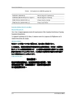
Appendix China RoHS Regulations .................................................................................. I
Appendix Figure I China RoHS Regulations .................................................................... I
List of Figures
Figure 1-1 Motherboard Overview ............................................................................ 1-2
Figure 1-2 Connectors and Component Locations of Motherboard ........................... 1-4
Figure 1-3 Back Panel LEDs ..................................................................................... 1-6
Figure 2-1 Screws Placement ................................................................................... 2-2
Figure 2-2 System Battery Location .......................................................................... 2-3
Figure 2-3 Pulling the System Battery out of the Holder ............................................ 2-3
Figure 2-4 Putting the System Battery into the Holder............................................... 2-3
Figure 2-5 Location of Processors ............................................................................ 2-4
Figure 2-6 Removing the Heat Sink .......................................................................... 2-4
Figure 2-7 Opening the Load Plate ........................................................................... 2-5
Figure 2-8 Lifting the Processor out of the Socket ..................................................... 2-5
Figure 2-9 Closing the Load Plate ............................................................................. 2-6
Figure 2-10 Installing the PnP Cap ........................................................................... 2-6
Figure 2-11 Pointing the Golden Corner toward the Socket....................................... 2-6
Figure 2-12 Location of System Memories ................................................................ 2-7
Figure 2-13 DIMM Socket Location ........................................................................... 2-8
Figure 2-14 Lifting the DIMM out of the Socket ....................................................... 2-10
Figure 2-15 Pressing the Retaining Clips Outward .................................................. 2-10
Figure 2-16 Inserting the DIMM into the Socket ...................................................... 2-10
Figure 3-1 PCH SSATA / PCH SATA Connector ........................................................ 3-1
Figure 3-2 PCH SATA Connector .............................................................................. 3-2
Figure 3-3 SATA SGPIO Connector .......................................................................... 3-3
Figure 3-4 MINI-SAS Connector ............................................................................... 3-4
Figure 3-5 Middle Plane Connectors ......................................................................... 3-6
Figure 3-6 Clear Password Jumper......................................................................... 3-10
Содержание B900G3
Страница 1: ...Board Manual B900G3 August 2015 Revision A P N 2015 MNU 000006 ...
Страница 3: ......
Страница 8: ......
Страница 18: ......
Страница 26: ...Hardware Operations 2015 MNU 000006 1 8 Off Turned off through IPMI command or by pressing down the button ...
Страница 27: ...Before You Start Screw Holes System Battery Processor System Memory Chapter 2 Hardware Operations ...
Страница 28: ......
Страница 29: ......
Страница 30: ......
Страница 38: ...Hardware Operations 2015 MNU 000006 2 8 Figure 2 13 DIMM Socket Location ...
Страница 42: ......
Страница 56: ......
Страница 57: ...Appendix China RoHS Regulations ...
Страница 58: ......
Страница 59: ......
Страница 60: ......
Страница 61: ...Appendix 2015 MNU 000006 I Appendix China RoHS Regulations Appendix Figure I China RoHS Regulations ...


