Introduction
2015-MNU-000006
1-5
1
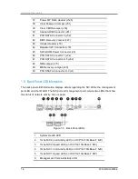
Power Button/LED (SW1)
2
VGA Connector (J39)
3
IPMB Connector (J62)
4
Host SMBus Connector (J52)
5
ME Upgrade Jumper (J63)
6
ID Button/LED (SW2)
7
BMC Reset Button (SW3)
8
Management Port (J50)
9
CPLD JTAG Connector (J60)
10
1Gbe NIC 1 (on OCP 1G/10G Base-T NIC)
11
1Gbe NIC 2 (on OCP 1G/10G Base-T NIC)
12
UART Connector (J29)
13
System Health LED
(CR1)
14
USB Port (J33)
15
QPI Slow Jumper (J58)
16
PCI-E x16 Slot (J37)
17
Mezz Slot 1 (J26)
18
Mezz Slot 2 (J57)
19
SATA SGPIO Connector (J41)
20
BMC Debug Connector (J44)
21
Power Debug Header (J70)
22
TPM Connector (J2)
23
SGPIO Connector (J71)
24
BP LED Connector (J72)
25
DIMM Slots for Processor 0 (J11, J12, J13, J14)
26
Processor 0 (U25)
27
XDP Connector (J46)
28
Processor 1 (U26)
29
DIMM Slots for Processor 1 (J15, J16, J17, J18)
30
PCI-E Mini-SAS Connector (J3)
31
Middle Plane Connector (J76, J77)
32
BP Mini-SAS Connector (J24)
33
DIMM Slots for Processor 1 (J19, J20, J21, J22)
34
Battery (BH1)
35
DIMM Slots for Processor 0 (J7, J8, J9, J10)
36
BP Power Connector (J64)
Содержание B900G3
Страница 1: ...Board Manual B900G3 August 2015 Revision A P N 2015 MNU 000006 ...
Страница 3: ......
Страница 8: ......
Страница 18: ......
Страница 26: ...Hardware Operations 2015 MNU 000006 1 8 Off Turned off through IPMI command or by pressing down the button ...
Страница 27: ...Before You Start Screw Holes System Battery Processor System Memory Chapter 2 Hardware Operations ...
Страница 28: ......
Страница 29: ......
Страница 30: ......
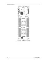
Страница 38: ...Hardware Operations 2015 MNU 000006 2 8 Figure 2 13 DIMM Socket Location ...
Страница 42: ......
Страница 56: ......
Страница 57: ...Appendix China RoHS Regulations ...
Страница 58: ......
Страница 59: ......
Страница 60: ......
Страница 61: ...Appendix 2015 MNU 000006 I Appendix China RoHS Regulations Appendix Figure I China RoHS Regulations ...


