background image


32 


Document Number 

DCV-00203 

Date Released 

Sept. 2016 

Revision Number/Security level 

R03 S2 

Retrofit G6+InvencoLink Wayne Vista (US) Installation Guide 

Note: DO NOT use the old screws from the pump door 

– they are too long.


Fig. 3.9 

 Frame screwed down 


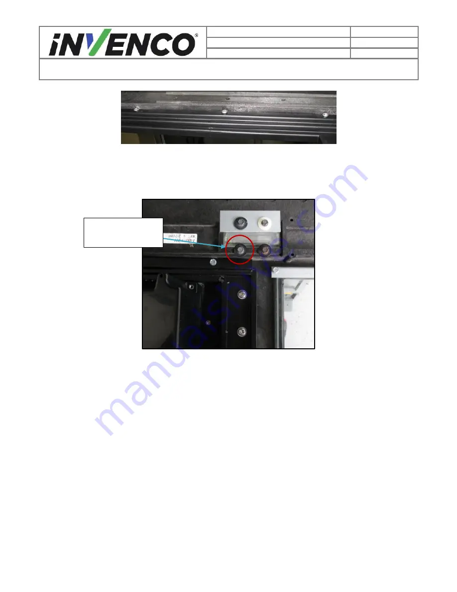
10.  For Narrow Frame Dispensers; re-install the Totalizer Window screw that was removed in Step 10 

of the Disassembly Procedure. (Fig 3.9.1)  


Fig. 3.9.1 

 Re-installing Totalizer Window Screw 


11.  Close and lock the RFK door to prevent it swinging during the rest of the installation process. 
12.  There will be an earth cable on the RFK door frame. Attach the cable to the dispenser door earth 

plate. Use the screw removed in Disassembly Step 10. Take care to route the wire around the 
earth plate, then tighten the screw. 

CAUTION

Excess cabling must be organized as to not cause obstruction when opening and closing 
the dispenser doors. Failure to properly restrain the wire assemblies may result in 
pinching and damaging them. IT IS THE RESPONSIBILITY AND THE DISCRETION OF 
THE INSTALLER TO PROVIDE AND INSTALL ANY CABLE RESTRAINTS THAT MAY 
BE NECESSARY TO FACILITATE THESE GUIDELINES. 


Screw retained 

from Disassembly 

Содержание G6 OPT

Страница 1: ...INSTALLATION INSTRUCTIONS NCR OPTIC 5 for Wayne Vista Release 1 0 497 0513342 Issue B ...

Страница 2: ...DCV 00203 Date Released Sept 2016 Revision Number Security level R03 S2 Retrofit G6 InvencoLink Wayne Vista US Installation Guide Retrofit G6 InvencoLink Wayne Vista US Installation Guide Kit Part Number 6001 0007 8801 ...

Страница 3: ...t 2 Dris Adradi September 2016 Minor updates from UL review PM 3 Adam Crocker September 2016 Revision to remove side specific BOM and reference InvencoLink Pre Installation to align the installation process with customer supply chain operation 2016 by Invenco Group Limited All rights reserved No part of this document may be copied or reproduced in any form without prior written consent from Invenc...

Страница 4: ...2 4 Evacuation Barricading and Shut Off 6 2 5 Read the Manual 6 2 6 Follow the Regulations 7 2 7 Replacement Parts 7 3 Safety Symbols and Terminology 7 3 1 Prevent Explosions and Fires 7 3 1 1 No Open Flames 8 3 1 2 No Sparks No Smoking 8 3 1 3 Working Alone 8 3 1 4 Working with Electricity Safety 8 3 1 5 Hazardous Materials 8 3 1 6 In an Emergency 8 3 1 7 Approvals 9 3 1 8 Laser Warning 9 3 2 Com...

Страница 5: ...requires the pre installation of UL Listed by Report Retrofit Kit Part Number 6009 0008 8801 InvencoLink Converter before installation into the dispenser The process is covered in 4 2 Pre Installation Procedure of this instruction by reference to the instructions in that Kit For a double sided installation two of these Kits are required 1 1 Tools Required The following tools are required to mount ...

Страница 6: ...ent G6 OPT IP0065 Mounted on RFK Door MP0551 PSU plate with cables EZ0408 Fishpaper insulating cover MP0588 Note color may vary Sundry Parts Comprising 4 MS0154 8 32 x 3 8 machine screws 3 MS0145 8g x 3 8 hex head screws 1 MF0046 Self Adhesive locking cable clip Cable Kit IA0031 Comprising clockwise from top left EK0126 Wayne Pump to Pump Adaptor 1 0m EK0127 Wayne Pump to InvencoLink 1 0m EK0131 C...

Страница 7: ... these should they be required Locate the switch or circuit breakers that shut off all power to all fuelling equipment and dispensing devices 2 3 Total Electrical Shut Off Before Access Any procedure requiring access to electrical components or the electronics of a pump dispenser requires total electrical shut off of that unit Understand the function and location of this switch or circuit breaker ...

Страница 8: ...bol is used in this manual and on warning labels to alert you to a precaution which must be followed to prevent potential personal safety hazard Obey safety directives that follow this symbol to avoid possible injury or death Signal Words These signal words used in this manual and on warning labels tell you the seriousness of particular safety hazards The precautions below must be followed to prev...

Страница 9: ...ith this requirement refer to information in the relevant manual and OSHA documentation 3 1 4 Working with Electricity Safety Ensure that you use safe and established practices in working with electrical devices Poorly wired devices may cause a fire explosion or electrical shock Ensure that grounding connections are properly made Take care that sealing devices and compounds are in place Ensure tha...

Страница 10: ...odels of the G6 OPT incorporate a barcode reader The barcode reader incorporates a laser aiming system The Laser has a Class 2 output power to IEC 60825 1 2007 ANSI Z136 1 CAUTION LASER RADIATION DO NOT STARE INTO BEAM 1mW MAX OUTPUT at 635 670nm CLASS 2 LASER PRODUCT4 3 2 Computer Programs and Documentation All Invenco Group Ltd computer programs including software on discs and within memory chip...

Страница 11: ...sembly The Printer The Printer Bracket The Water Catch Tray The Q Cat Board Various Cable Assemblies 1 At the main disconnect panel disconnect all power to the dispenser and the pump servicing the dispenser Tag all disconnected breakers to prevent others from reconnecting power 2 Identify the Side A of the dispenser Note For the purposes of this manual Side A of the dispenser refers to the side wi...

Страница 12: ...vencoLink Wayne Vista US Installation Guide Fig 2 1 Wide Frame top Side A of Electronics Bezel Narrow Frame bottom 4 Lower the electronics head bezel by pulling the top forward until it fully rests on the suspension cables 5 Locate the Graphic Display Assembly or Single Line Display Fig 2 2 Security Bolts ...

Страница 13: ...vencoLink Wayne Vista US Installation Guide Fig 2 2 Electronics Bezel in fully lowered position 6 For the Graphic Display Assembly Unplug the 8 pin display cable and the two wire ribbon cable that are connected to the Graphic Display Assembly Fig 2 3a Graphics Display Assembly Single Line Display Assembly ...

Страница 14: ...Line Display Unplug the 40 pin display cable and the two wire grey cable that are connected to the Single Line Display Assembly Fig 2 3b Fig 2 3b Location of both Single Line Display cables that will need unplugged The remaining cables are attached to peripheral components that will be removed along with the Display Assembly later in the disassembly process Two Wire Ribbon Cable 8 pin Display Cabl...

Страница 15: ...Fig 2 4a Fig 2 4a Location of the 3 screws that need removal Note There may be a variant design for the Card Reader Rain Catcher The process for removing the Graphic Display Assembly is identical to the one in Step 8 with the exception that the rain catch has TWO screws fastening it instead of ONE However only one of these screws will need to be removed A 5 long screwdriver will be needed to reach...

Страница 16: ...ion of the ground strap screw 10 Remove the Display Assembly from the electronics head bezel by lifting the bottom of it up and out Set the assembly aside to be discarded Fig 2 6 Note For Narrow Frame Dispensers you may need to remove one of the Totalizer Window screws in order to make clearance when removing the Display Assembly Remove this screw and retain it It will be re installed later during...

Страница 17: ...R03 S2 Retrofit G6 InvencoLink Wayne Vista US Installation Guide Fig 2 5 1 Remove Totalizer Window Screw Narrow Frame only Fig 2 6 Grab the card reader and remove the assembly 11 Remove the Printer Assembly 1 Slide the printer forward until it stops Fig 2 7 Remove and retain this screw ...

Страница 18: ...Link Wayne Vista US Installation Guide Fig 2 7 Printer in the fully pulled out position 2 Unplug both cables from the back of the printer Fig 2 8 Fig 2 8 Remove both printer cables 3 Lift up on the release tab inside the printer assembly and firmly pull the printer forward to remove it Fig 2 9a b Printer Cables ...

Страница 19: ... Revision Number Security level R03 S2 Retrofit G6 InvencoLink Wayne Vista US Installation Guide Fig 2 9a Location of Printer Release Tab Fig 2 9b Printer Slide after Printer has been removed 4 Set the printer aside to be discarded Printer Release Lever ...

Страница 20: ...ng it up and out of the electronics cabinet Set it aside to be discarded Fig 2 11 Fig 2 11 Removal of water catch tray 13 Open Side B of the pump using steps 3 4 above Depending whether you have a Wide or Narrow Frame pump follow one of the next two steps below then continue 14 Remove the Printer Bracket in a Wide Frame Pump 1 Remove the two Philips head screws from Side A of the dispenser and the...

Страница 21: ...racket Screws Wide Frame 2 Cut or unfasten any cord restraints or zip ties that may be fasten to the printer s bracket You may have to check for cable ties from both sides of the dispenser 3 Turn and remove the printer bracket from the electronics cabinet Set it aside to be discarded Fig 2 13 Fig 2 13 Electronics Cabinet after removal of Printer Bracket A Printer Bracket Screws B ...

Страница 22: ...e two Philips head screws from each side of the Printer Bracket using the pictures as a guide The screws can be discarded Fig 2 14 Fig 2 14 Side A Side B Printer Bracket Screws Narrow Frame 2 Cut or unfasten any cord restraints or zip ties that may be fasten to the printer s bracket You may have to check for cable ties from both sides of the dispenser Fig 2 15 is an example photo only A Printer Br...

Страница 23: ...encoLink Wayne Vista US Installation Guide Fig 2 15 Remove any zip ties or cable restraints 3 Lift and remove the printer bracket from the electronics cabinet Set it aside to be discarded Fig 2 16 Fig 2 16 Electronics Cabinet after removal of Printer Bracket 16 Remove the Q CAT board if present Cut Zip ties ...

Страница 24: ...vencoLink Wayne Vista US Installation Guide 1 Unplug all wiring that is attached to the Q CAT board The Purple Brown cable is used for communications It must be marked and retained for later use 2 Remove the 4 Philips head hold down screws on the Q CAT board Discard the screws Set Screws Retain this cable ...

Страница 25: ...d Graphics Display Assembly Cut any zip ties and remove any cable restraints that may be present 17 If the dispenser is two sided repeat steps 5 16 for Side B of the dispenser Otherwise continue 18 The disassembly process is complete The dispenser is now ready for the Pre Installation procedure to begin All removed components can be discarded Wide Frame set above Graphics Display Assembly Printer ...

Страница 26: ... 2016 Revision Number Security level R03 S2 Retrofit G6 InvencoLink Wayne Vista US Installation Guide All removed components can be discarded Narrow Frame set above Graphics Display Assembly Printer Bracket Assembly Printer Assembly Water Catch Tray ...

Страница 27: ...tions methods are listed below UL Report Number Kit Part Number Retro Fit Kit Description MH61528 6009 0008 8801 InvencoLink DSP232 For Side B i e the second side you MUST have Side A i e the first side already installed and you may then proceed to 4 3 Installation Procedure For Side A i e the first side select the PSU Plate Assembly from this Retro Fit Kit package and apply the communications met...

Страница 28: ...oLink converter installed a Place the plate up against the standoffs on the left side of the cavity b Secure the plate in place using four MS0154 8 32 3 8 screws and a Philips head screwdriver Fig 3 1 Side A PSU Plate installation position Side B 2 Plug the patch cables into the InvencoLink converter sockets a For Side A the converter will be on the plate you have just installed i Plug the EK0129 ...

Страница 29: ...arily coil the loose ends of the four cables Black low voltage DC Green Yellow Earth Red and Yellow patch in the bottom of the pump cabinet Fig 3 1 2 Fig 3 1 2 Identifying Earth Ground and DC Cables 4 Unlock the MP0551 RFK door and open the frame thru 180 Pass the RFK door upwards through the opening in the pump door Note the orientation of the OPT Black DC Voltage Cable Green Yellow Earth Ground ...

Страница 30: ...S Installation Guide Fig 3 3 Bringing the frame through the opening 5 Turn the RFK door thru 90 and while holding the OPT gently manipulate the RFK frame into a flatter position over the opening ensuring the three screw holes are positioned at the bottom i e closest to the pump door hinge Fig 3 4 Midway through seating the frame ...

Страница 31: ... frame under the three lugs at the top taking care moving it past the pump door retainer cable fastening bolt on the left in the above photo Note that the thickness of the sealing gasket will make the frame tend to sit quite high Fig 3 5 Frame partially seated Fig 3 6 Close up of a lug 7 Wiggle the RFK frame carefully to move it under the frame of the glass window ...

Страница 32: ... of the window frame 8 Then carefully work the rest of the RFK frame into the pump door opening and press it down to seat it fully Fig 3 8 Seating the frame 9 Screw the RFK frame to the pump door using three MS0145 8 3 8 sheet metal hex head screws and a nut driver You may have to press down on the RFK frame to squeeze up the gasket before you can start the screws ...

Страница 33: ...t swinging during the rest of the installation process 12 There will be an earth cable on the RFK door frame Attach the cable to the dispenser door earth plate Use the screw removed in Disassembly Step 10 Take care to route the wire around the earth plate then tighten the screw CAUTION Excess cabling must be organized as to not cause obstruction when opening and closing the dispenser doors Failure...

Страница 34: ...4 and 15 the cable retention bracket is loose and may fall if care is not given when proceeding Fig 3 11 Cable retention bracket retaining screws 14 Take the cable ends previously coiled into the cavity in the pump cabinet and connect them to the OPT a Feed the low voltage DC cable through the square opening in the cable retention bracket then plug it into the OPT Fig 3 12 Low voltage DC Cable con...

Страница 35: ...side you re working on e g Side A Fig 3 13 Patch Cable connection c Connect the Green Yellow Earth cable from the Power Supply Assembly to the tab on the OPT paper holder frame Fig 3 14 Plug in earth cable 15 Re install tighten the screws removed in step 13 on the cable retention bracket 16 Gather all of the cables that are attached to the OPT unit including the Green Yellow Earth that was install...

Страница 36: ...d secure them into a MF0046 self adhesive cable clip Stick the clip onto the dispenser door below the central screw at the bottom of the RFK frame Fig 3 16 Place cable clip 18 Loosen the two screw catches on the Side A Sale Calculator by turning them turn counter clockwise Fig 3 17 Loosen the Sale Calculator screws 19 Gently open the calculator down toward the pump door until it rests on the pump ...

Страница 37: ...e Vista US Installation Guide Fig 3 18 Sale Calculator opened down 20 Disconnect the mains input connector 4 Pin on the left side of the Dispenser Electronics Module Fig 3 19 Unplugging the mains input connector 21 Insert the EK0126 Mains Cable by connecting the double connector end into the above connection 4 Pin Mains ...

Страница 38: ...tions 22 Insert the other connector into the fixed connector on the Dispenser Electronics Module Fig 3 21 Second of two connections 23 Lay the unconnected end of the EK0126 Mains Cable in the bottom of the pump cavity near the EZ0408 PSU Plate Assembly associated with the side you re working on 24 Install the MP0588 fish paper cover over the Sale Calculator power supply board ...

Страница 39: ...yne Vista US Installation Guide Fig 3 22 Sale Calculator Power Supply Board and connections a Unplug the connectors P5 P6 from J5 J6 Fig 3 23 P5 P6 disconnected b Use a Philips head screwdriver to loosen the four screws that retain the power supply mounting bracket You need a gap of about 1 16 under the head s washer ...

Страница 40: ... 3 24 Left above right top screws to loosen Fig 3 25 Screw loosened c Place the fish paper insulator over the power supply board under the cables terminated in P5 P6 and note the orientation Fig 3 26 Fish paper insulator in place d Ensure the insulator goes under the head of each of the four screws loosened in b and is fully pressed down P5 P6 this end ...

Страница 41: ...en the four screws loosened in b f Re plug the connectors P5 P6 into J5 J6 Fig 3 28 P5 P6 reconnected 25 Gently restore the calculator to its normal position Be sure no wires are pinched when setting the calculator in place Tighten the screw catches by turning them turn clockwise 26 Connect the end of the EK0126 Mains Cable into the connector on the EZ0408 PSU Plate Assembly of the side you re wor...

Страница 42: ...only a Connect female end of the EK0127 two wire communication cable into the pump s communication loom the connector marked in disassembly Step 16 1 Fig 3 30 Two Wire Cable connected to Pump Loom b Route the EK0127 cable through the bottom of the pump cabinet to the EZ0408 PSU Plate Assembly that contains the InvencoLink converter and plug the other end of the cable into the LINE port on the Inve...
Страница 43: ...he no cables are pinched and both the bolts on each door are properly fastened using the special Wayne Security Key 4 3 1 Wiring Completion When all the cables have been installed use cable ties to provide strain relief The rear of the G6 OPT has plastic loops close to the connectors that are intended to assist with this Also ensure that all cables are tidy and cannot become snagged or pinched whe...

Страница 44: ... G6 OPT takes a couple of minutes to complete its start up phase during which several information screens will be presented The terminal will display the following screen whilst attempting to connect to the LAN This screen will persist until a connection can be made If the terminal is successful in connecting to the LAN it will display the following screen and the rest of the start up sequence wil...

Страница 45: ...ll in place the paper tension flap is spring loaded so you will need to apply some pressure Insert the spindle through the middle of the roll to hold in place 3 Insert the cut edge of the paper into the slot as shown in the photo opposite Note Insert until the printer grips and feeds automatically 4 The photo opposite shows the paper loaded 5 The photo opposite shows the feed button Press either b...

Страница 46: ... Revision Number Security level R03 S2 Retrofit G6 InvencoLink Wayne Vista US Installation Guide 6 Feed the paper through the terminal until it appears at the paper exit slot Cut the paper using both feed buttons and remove the cut length from the chute ...

Отзывы: