background image

Dahlia®30 / 45

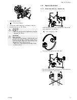
4.

G

C

Remount the tilt handle

G

on the holder and re-attach the screw

C

. Repeat the procedure on the opposite side.

5.

H

Loosen the nut

H

on the wire from the brake handle. Repeat the

procedure on the opposite side.

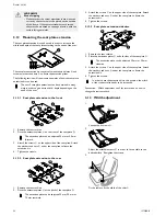
6.

I

Loosen the nut

I

for the brake wire holder. Repeat the

procedure on the opposite side.

7.

J

K

Push the wire tightener

J

towards the wire holder in order

to loosen the wire of the hand operated brake

K

. Repeat the

procedure on the opposite side.

8.

K

L

Loosen the hook

L

at the end of the wire and remove the wire

K

from the wire holder. Repeat the procedure on the opposite

side.

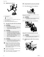
9.

M

Mount the foot maneuvered brake

M

on the back frame of the

wheelchair.

The foot maneuvered brake is always mounted on the
left side.

10.

P

N

O

Mount the wire for the foot maneuvered brake

N

in the wire

holder on the wheel and thread the hook

O

through the wire

tightener

P

.

11.

R

Q

Tighten the nut for the brake wire holder

Q

and the nut on

the wire

R

to secure the wire. Repeat the procedure on the

opposite side.

14

1572308-B

Содержание Dahlia 45

Страница 1: ...Dahlia 30 45 en Manual wheelchair passive Service Manual DEALER Keep this manual The procedures in this manual MUST be performed by a qualified technician Dahlia 45 ...

Страница 2: ...cation duplication or modification in whole or in part is prohibited without prior written permission from Invacare Trademarks are identified by and All trademarks are owned by or licensed to Invacare Corporation or its subsidiaries unless otherwise noted ...

Страница 3: ... seat width 19 3 9 Rear wheels 19 3 10 Adjusting the seat height and balance point with the rearwheel attachment 19 3 10 1 Rearwheel attachment standard position 19 3 10 2 Turning the rearwheel attachment 20 3 10 3 Rearwheel attachment mounted on the opposite side 20 3 10 4 Rearwheel attachment turned opposite sides 20 3 10 5 Rear wheel attachment depth adjustment 20 3 11 Castor attachment 21 3 11...

Страница 4: ...may not function properly Changes to the wheelchair should only be carried out by trained personnel For pre sale and user information please see the user manual The user manual can be found on Invacare s website 1 2 Delivery check Any transport damage must be reported immediately to the transport company Remember to keep the packaging until the transport company has checked the goods and a settlem...

Страница 5: ... a new screw must be used the old one must be scrapped 4 4x x4 D E F Loosen the four screws for the backrest tubes D and turn the attachments E in order to release the backrest tube F Do not remove the screws 5 H 2x G Mount the attachments for the MatrX backrest G and tighten the screws H Tools 5 mm Allen key 6 2x I J Mount the backrest tubes I on the attachment knobs J on the backrest Start with ...

Страница 6: ...ires under the seat to get them out of the way 2 2 2 Wires with tension adjustable backrest A B C C D E 1 Place the wires A and B as shown on the picture above Risk of damage to the wires It is important that the cable for the assistant brake A is placed on the inside of the backrest tubes 2 Place the wire for the backrest seat recline B outside of the backrest tubes 3 Place both of the wires on t...

Страница 7: ...chment part facing outwards The plain surface B of the attachment should be placed upwards when using the table on the thin armrests 2 A C To fit the table attachment A to the wide armrest turn the attachment around the patterned surface C should now be facing upwards 2 6 Mounting the table tray A B Mount the table tray A in the table tray attachments B 2 7 Mounting the rear wheels B A C 1 Press a...

Страница 8: ... Remove the armrest pad F from the standard armrest attachment tube and place it in the new armrest tube E Tighten the screw G Mount the lever for the user operated tilt H below the armrest pad in the front of the pad Tighten the screw screws Place the wire between the armrest pole and the side rest One or two attachment screws are used depending on the thickness of the armrest pad 6 8 I J K L Loo...

Страница 9: ...ing to the gas piston For the Dahlia 30º version the reduction bushings can be used to reduce both the tilt and the recline range For the Dahlia 45º version the reduction bushings will reduce the recline range with 10º or 20º and the reduction blocks will reduce the seat tilt range from 45º to 30º CAUTION Risk of damage Removing the reduction bushings could cause damage to the wheelchair in some p...

Страница 10: ... B C Remove the upper screw A and the lower screw and washer B Remove the ordinary legrest attachment C Tools Screwdriver PH 2 for screw A allen key 5 mm for screw B 2 D B A Mount the high legrest attachment D in the seat frame Re insert the upper screw A and the lower screw and washer B Re tighten the screws Tools Screwdriver PH 2 for screw A allen key 5 mm for screw B 2 13 Mounting the accessory...

Страница 11: ...e attachment G on the frame Attach the nuts H and the screw I 4 J K L Mount the wire hook from the brake handle in the wire holder J Mount the wire in the attachment washer K and place the wire in the lower notch on the brake L WARNING Risk of injury Poor brake effect Check the brake effect after mounting or adjusting the brake 2 14 2 Drum brake for 22 24 1 A B C Mount the handle for the assistant...

Страница 12: ...and tighten the screws D 18 24 Nm 3 E Mount the quick release attachments E and the nuts and washers 4 F Mount the rearwheels F in the quick release attachments 5 G H Press the telescopic rearwheel shaft G together and place it between the rearwheel axles H 6 G I Mount the telescopic rearwheel shaft G on the rearwheel axles and release the pressure to fixate the shaft Pull the quick release knob I...

Страница 13: ... it away from your body when you release the steel spring inside 2 17 Mounting the foot operated brake 1 A B Loosen and remove the screws A for the brake and tilt handle B and remove the handle Repeat the procedure on the opposite side 2 C D E Loosen the screw C on the brake and tilt handle and remove the tilt handle D and the cap E Repeat the procedure on the opposite side 3 E A F Separate the br...

Страница 14: ...erated brake K Repeat the procedure on the opposite side 8 K L Loosen the hook L at the end of the wire and remove the wire K from the wire holder Repeat the procedure on the opposite side 9 M Mount the foot maneuvered brake M on the back frame of the wheelchair The foot maneuvered brake is always mounted on the left side 10 P N O Mount the wire for the foot maneuvered brake N in the wire holder o...

Страница 15: ...UTION Risk of pinching When adjusting the height these is a risk of pinching your finger Be careful when adjusting the height A B A Upper screws for additional height adjustment B Lower screws for additional height adjustment For additional height adjustment 50 mm 1 Loosen screws 2 Set the required height 3 Re tighten the screws Tools 5 mm Allen Key 3 1 2 Width adjustment backrest plate WARNING Ri...

Страница 16: ...rnative 2 A B C D A to D Screws for alternative height adjustment Tools 5 mm Allen Key An additional height adjustment can be made by mounting the backrest attachment either in position A and C or in position B and D on the backrest tubes as shown in the picture above 0 1 2 3 4 0 1 2 3 4 0 1 2 3 4 0 1 2 3 4 A B C A Tools 5 mm Allen Key 1 Remove the screws and the washers A the long nut B and the b...

Страница 17: ...onger angle of the backrest is turned upwards B Position B The longer angle of the backrest is turned downwards A A A Screws for adjustment of the backrest tubes Tools 5 mm Allen Key 3 3 3 Angle adjustment Tension adjustable backrest 0 1 2 3 4 0 1 2 3 4 A The backrest tubes can be angled individually the indication labels A on the backrest tubes are a help in order to get the same angle on both si...

Страница 18: ... 6 Armrest 3 6 1 Adjusting the armrest height A 1 Adjust the height of the armrests and or side rests by turning the screw or the hand wheel A depending on which type of armrest you have chosen 2 Set the required height 3 Re tighten the screw hand wheel CAUTION Risk of trapping fingers Be careful not to trap your fingers between the armrest side support pad and the armrest attachment when adjustin...

Страница 19: ...er to propel Test the different settings to see what suits you best WARNING Risk of tipping The risk of tipping increases when the rear wheels are moved forward Always use anti tip devices WARNING Safety risk When you have fitted the wheels in the correct position it is important that you check thoroughly that the nuts and screws are tightened securely This is important for your own safety CAUTION...

Страница 20: ...ties By doing this the seat height and the placement of the rearwheels can be changed even more See section Turning the rearwheel attachment for instructions about how to demount and remount the rearwheel attachment Remount the rearwheel attachment on the opposite side instead of on the same side 3 10 4 Rearwheel attachment turned opposite sides When the rearwheel is mounted on the opposide side c...

Страница 21: ...n and large rearwheels are used there is a risk of pinching the fingers as the distance between the rear wheel and the armrest is too small Move the rear wheel attachment backwards in order to reduce the risk 3 11 Castor attachment 3 11 1 Castor attachment adjustments 1 A B B C Loosen and remove the screws A and the nuts B Remove the castor attachment C on both sides Tool Hexagon key 5 mm 2 Turn t...

Страница 22: ...he seat plate Attach the washers and nuts B under the seat plate to fixate the extension kit 4 Tighten the screws 3 12 2 Seat plate extension to the rear B B C C D A 1 Remove the seat cushion 2 Place the extension plates A at the back of the seat plate D The extension plate can be adjusted 25 mm 50 mm or 75 mm rearward 3 Attach the screws C on the upper side of the seat plate Attach the washers an...

Страница 23: ...esired angle 3 Retighten the screw 4 Repeat this procedure to adjust the angle of the other foot plate 3 15 3 Adjusting the depth of the central legrest A 1 Loosen the frontal screw A on the side of the tube Tools 5 mm Allen key 2 Adjust the depth of the foot plate 3 Tighten the screw A when you have found the desired depth 4 Repeat this procedure to adjust the depth of the other foot plate 3 15 4...

Страница 24: ... sliding risk Belts which are CE marked for the purpose of using on wheelchairs can be mounted on the chair with preserved CE marking The belts should be fitted by the responsible prescriber and be mounted by an experienced technician However when transporting the wheelchair in a vehicle Invacares original pelvic belt must be used as a complement to the safety belt in the vehicle The purpose of a ...

Страница 25: ...ct braking effect the brake pin should press into the tire when you apply the brake The brake may therefore require depth adjustment WARNING Risk of reduced brake effect Incorrect setting or use of the brake reduces the braking effect A B C Tool 5 mm Allen key 1 Loosen the screw A 2 Move the brake attachment to the required position 3 Re tighten the screw A There should be a distance of approximat...

Страница 26: ...Foot maneuvered brake adjustments 1 A Adjust the brake effect with the adjustment nut A on the wire 2 B B When the desired brake effect is achieved fixate the brake wire with the fixation nut B WARNING Risk of injury Poor brake effect Check the brake effect after mounting or adjusting the foot maneuvered brake 26 1572308 B ...

Страница 27: ...he fabric may be neutralized with a soft damp cloth and some neutral detergent To neutralize larger more persistent stains wipe the fabric with alcohol or turpentine substitutes and wash with hot water and a neutral detergent Proprietary disinfectants may be used provided that the manufacturer s instructions are followed The fabric can be washed at temperatures up to 71º C 160º F Normal detergents...

Страница 28: ...u have the correct air pressure in the tires to attain the optimal brake effect Castors Detach the castors and clean the castor forks Remove any dirt or hair from the castors Attach the castors again and check that the castors turn freely If the castors are air filled check the pressure recommended air pressure for low profile tires is 8 4 0 bar If the castors are solid check the tires for cracks ...

Страница 29: ...er Seat cover Seat angle Carer operated brake Armrests Side rests Legrests Footrests Anti tip device Rear wheels Rear wheel attachment Brakes Castors Fasteners for wear and tightness Headrest Neckrest Trunk support Abduction cushion Table tray TEST Chair rolls in straight line Easy to propel DELIVERY CHECK Include a user manual 1572308 B 29 ...

Страница 30: ...in the chairs are produced of Thermoplastic and are marked with recycling symbols where it is possible due to part size The main plastic material is polyamide The plastic materials for the table are ABS and polyamide This material can be recycled or burned in approved facilities Upholstery Upholstery is produced of polyester fibres PUR and Dartex The efficient way to recycle the parts is to burn t...

Страница 31: ...C Possible solutions Move the seat plate D forwards to increase the seat depth Move the rear wheel attachment C further backwards Turn the rear wheel attachment C in order to have the rear wheel positioned further backwards Choose the low mounting position for the rear wheel attachment C This will increase the seat height to compensate use a longer front wheel fork A Use the tilt reduction bushing...

Страница 32: ...2 380 450 mm 350 500 mm 3 24 430 450 mm 24 450 480 mm 4 500 800 mm 500 800 mm 500 800 mm 500 800 mm 5 250 320 mm 250 320 mm 250 320 mm 250 320 mm 6 330 500 mm 330 500 mm 330 500 mm 330 500 mm 7 1 30º 1 30º 0 45º 0 45º 8 SW 180 mm SW 160 mm SW 180 mm SW 160 mm 9 825 1250 mm 825 1250 mm 850 1250 mm 850 1250 mm 10 900 1180 mm 900 1180 mm 900 1180 mm 900 1180 mm 11 35 kg 35 kg 35 kg 35 kg 12 135 kg 13...

Страница 33: ...operating conditions before use 7 3 Seat height tables Seat height table Dahlia 30 degrees Seat height Wheel Position of rear wheel attachment STD Position of rear wheel attachment High Fork 150 Castor housing Position Fork 110 Castor housing Position Position of brake attachment 1 2 3 4 5 6 2 1 2 1 1 2 3 4 330 16 1 NA NA NA 3 100 2 3 330 20 6 NA NA NA 3 100 2 1 350 16 3 NA NA NA 2 125 2 4 350 20 ...

Страница 34: ...480 16 30 30 30 30 500 20 30 30 30 30 Measured from floor to seat plate cushion excluded Seat height table Dahlia 45 degrees Seat height Wheel Position of rear wheel attachment STD Position of rear wheel attachment High Fork 150 Castor housing Position Fork 110 Castor housing Position Position of brake attachment 1 2 3 4 5 6 2 1 2 1 1 2 3 4 350 16 1 NA NA NA 3 100 2 3 350 20 6 NA NA NA 3 100 2 1 3...

Страница 35: ...ngs on backrest piston Delivered from factory Max tilt possible Delivered from factory Max recline possible 350 16 45 45 30 30 350 20 30 30 Yes 30 30 380 16 45 45 30 30 380 20 45 45 10 30 2 380 22 30 30 Yes 30 30 400 20 45 45 30 30 430 20 45 45 30 30 430 22 45 45 30 30 450 22 45 45 30 30 450 24 45 45 30 30 480 16 45 45 30 30 480 24 45 45 30 30 500 16 45 45 30 30 Measured from floor to seat plate c...

Страница 36: ... Fax 353 1 810 7085 ireland invacare com www invacare ie United Kingdom Invacare Limited Pencoed Technology Park Pencoed Bridgend CF35 5AQ Tel 44 0 1656 776 222 Fax 44 0 1656 776 220 uk invacare com www invacare co uk Manufacturer Invacare Rea AB Växjövägen 303 S 343 75 Diö 1572308 B 2014 09 30 1572308B Making Life s Experiences Possible ...

Отзывы: