background image

SECTION 2—OPERATION

IVC

Bed Series

16

Part No 1114836

FIGURE 2.3   

Using the Emergency Crank - Operating Full Electric Bed - Models 5410IVC and 

5411IVC

Operating the Manual Bed

NOTE: For this procedure, refer to FIGURE 2.4.

1. Perform one of the following: 

• Raise or lower the head section with crank "A"

• Raise or lower the foot section with crank "C".

• For Model 5307IVC only - Raise or lower the entire bed with crank “B”.

2. Test all operating features of the bed.

3. If any problems arise during testing, recheck all mechanical hook ups.

FIGURE 2.4   

Operating the Manual Bed - Model 53071IVC

Optional Bed Rails 


WARNING

DO NOT install the optional bed rails without reading and understanding all of the 

instructions in the instruction sheet that accompanies the bed rail kit.

NOTE: Link Fabric 
not shown.

A - Head Section

B - Entire Bed

C - Foot Section

NOTE: Link Fabric 
not shown.

Crank “A”

Crank “B”

Crank “C”

Содержание 5310IVC

Страница 1: ...en to the user of the product USER BEFORE using this product read this manual and save for future reference For more information regarding Invacare products parts and services please visit www invacar...

Страница 2: ...care products are specifically designed and manufactured for use in conjunction with Invacare accessories Accessories designed by other manufacturers have not been tested by Invacare and are not recom...

Страница 3: ...VC and 5411IVC 13 Raising and Lowering the Entire Bed 13 Raising and Lowering the Head and Foot Sections 14 Operating the Semi Electric Bed Models 5310IVC and 5311IVC 14 Raising and Lowering Head and...

Страница 4: ...ving Cable Lock 30 Installing the Manual Crank for Hi Lo Function 31 Installing Removing the Pendant 32 Storing the Beds 32 SECTION 5 TROUBLESHOOTING 33 Troubleshooting Electrical 33 Troubleshooting M...

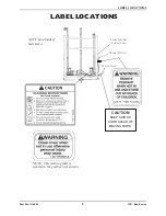
Страница 5: ...114836 5 IVC Bed Series LABEL LOCATIONS CAUTION KEEP SWITCH CORD CLEAR OF MOVING PARTS Pendant Cord Power Cord NOTE Underside of bed shown NOTE This warning label is located on the gearbox not shown S...

Страница 6: ...more than one function button at a time If thermal protection activation should occur the bed will not respond to pendant commands Given this situation release the pendant button and allow the bed un...

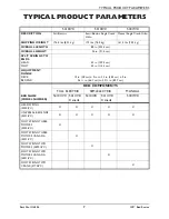
Страница 7: ...RINGS TO ENDS HEAD FOOT 43 in 109 2 cm 45 in 114 3 cm ADJUSTMENT RANGE DECK BED END 15 in 38 cm 2 in to 23 in 58 3 cm 2 in 26 in 66 7 cm to 33 in 85 7 cm BED COMPONENTS FULL ELECTRIC SEMI ELECTRIC MAN...

Страница 8: ...tric bed before cleaning Clean up the spill and allow the electric bed or the area around the electric bed to dry thoroughly before using the electric controls again The manual electric bed is NOT des...

Страница 9: ...ntrapment Variations in bed rail dimensions and mattress thickness size or density could increase the risk of entrapment Visit the FDA website at http www fda gov to learn about the risks of entrapmen...

Страница 10: ...ce of entrapment the bed MUST be in the flat position when left unattended After raising lowering the head foot end of the manual electric bed check the distance between the bottom of the bed rail and...

Страница 11: ...ervicing to qualified personnel only Grounding reliability depends upon a properly grounded wall outlet Repair or Service Information DO NOT open assemblies such as the motors pendant junction boxes o...

Страница 12: ...s also able to be marked on the product Radio Frequency Interference Electronic equipment may be influenced by Radio Frequency Interference RFI Caution should be exercised with regard to the use of po...

Страница 13: ...te Simply release the pendant button permit a slight pause and then activate the next operation On Full Electric beds the Hi Lo crank MUST be removed before the bed is placed in service If left in pla...

Страница 14: ...IVC NOTE For this procedure refer to FIGURE 2 2 1 Perform one of the following Use a four function pendant for head and foot spring functions Use a hand crank for Hi Lo bed operation 2 Test all operat...

Страница 15: ...to be adjusted manually due to a power outage or an electronic malfunction use the emergency crank to make the adjustments You should find the Emergency crank stored in the link fabric of the spring...

Страница 16: ...C For Model 5307IVC only Raise or lower the entire bed with crank B 2 Test all operating features of the bed 3 If any problems arise during testing recheck all mechanical hook ups FIGURE 2 4 Operating...

Страница 17: ...hed Call the dealer for repair replacement of cables and or motors Broken cable lock Call dealer to replace cable lock Household fuse or breaker blown Check household fuse breaker box Motors are not f...

Страница 18: ...sections for bending warping or damage Inspect all bolts and rivets to ensure that they are securely tightened and functioning properly Check sleep surfaces to ensure all links are intact Check caste...

Страница 19: ...d and free of damage Make sure cable lock on junction box is properly positioned and locked Check all functions Head raises and lowers properly Foot raises and lowers properly Bed Ends raise and lower...

Страница 20: ...Procedures Receiving Unpacking Unpacking the Bed Ends Unpacking Foot and Head Spring Sections Set Up Assembling the Head and Foot Spring Sections Assembling the Spring Fabric Adjusting and Reconnectin...

Страница 21: ...nvacare Customer Service department Unpacking NOTE Check all parts for shipping damage In case of shipping damage DO NOT use Contact Dealer Carrier for further instruction CAUTION DO NOT plug the powe...

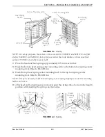
Страница 22: ...ntrols prior to completion of assembly as dam age to bed components or personal injury may occur NOTE For this procedure refer to FIGURE 4 3 and FIGURE 4 4 on page 23 4 Remove the head spring section...

Страница 23: ...unting rivet Refer to FIGURE 4 4 11 Hook the top head spring center mounting latch to the top foot spring center mounting rivet Refer to FIGURE 4 4 NOTE It may be necessary to lift the head spring or...

Страница 24: ...e NOTE For this procedure refer to FIGURE 4 6 on page 25 1 To disconnect the head pull tube assembly from the side frame of the foot spring remove the hitch pin grommet washer from the clevis pin Refe...

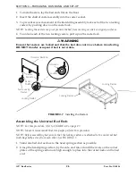
Страница 25: ...NOTE ALWAYS locate locking caster in the same location on each bed end so that they will always be assembled diagonally opposite each other when inventory is mixed NOTE Position the two locking caster...

Страница 26: ...sferring DO NOT transfer occupant if bed is not stable FIGURE 4 7 Installing the Casters Assembling the Universal Bed Ends NOTE For this procedure refer to FIGURE 4 8 on page 27 NOTE Invacare recommen...

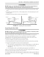
Страница 27: ...Lo function consists of two sections that are shipped unassembled The inner shaft has a positioning spring button and the outer shaft has three positioning holes one storage position hole and a telesc...

Страница 28: ...x ii Ensure the Hi Lo motor output shaft spring loaded coupler is properly aligned with the foot end gear box as shown in Detail A of FIGURE 4 10 iii Release the Hi Lo motor output shaft spring loaded...

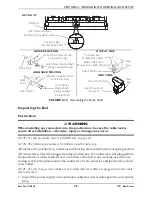
Страница 29: ...g use the color coding to check the placement of the connectors Each connector and junction box slot is color coded NOTE The color rings on the cables are not visible when the cables are plugged in an...

Страница 30: ...Manual Beds 1 Raise and lower the cranks at the foot of the bed to make sure they work correctly Refer to Operating the Manual Bed on page 16 2 If no damage is found set up the bed for use 3 If damag...

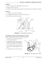
Страница 31: ...emoving Cable Lock Installing the Manual Crank for Hi Lo Function NOTE For this procedure refer to FIGURE 4 13 on page 31 1 Pinch the ears on the input drive shaft cover to open the cover 2 Flip the i...

Страница 32: ...the electric bed unscrew the union nut on the standard pendant cable that attaches to the extension cable 2 Unplug the standard pendant cable from the extension cable FIGURE 4 14 Installing Removing...

Страница 33: ...age 27 Ensure cables are not entangled pinched Call Invacare for repair replacement of cables and or motors Broken cable lock Call Invacare to replace cable lock Hi Lo Motor Ensure Hi Lo motor cable i...

Страница 34: ...ioning properly Check sleep surfaces to ensure all links are intact Check casters to ensure they lock if applicable and roll properly SYMPTOM PROBABLE CAUSE SOLUTIONS Bed does not stay in place Lockin...

Страница 35: ...damage Make sure cable lock on junction box is properly positioned and locked Check all functions A Ensure head raises and lowers properly B Ensure foot raises and lowers properly C Ensure bed ends r...

Страница 36: ...ents who have problems with memory sleeping incontinence pain uncontrolled body movement or who get out of bed and walk unsafely without assistance must be carefully assessed for the best ways to keep...

Страница 37: ...xt to the bed as long as this does not create a greater risk of accident Use transfer or mobility aids Monitor patients frequently Anticipate the reasons patients get out of bed such as hunger thirst...

Страница 38: ...pecific hospital bed contact the bed manufacturer directly Developed by the Hospital Bed Safety Workgroup Participating Organizations AARP ABA Tort and Insurance Practice Section American Association...

Страница 39: ...hased your Invacare product In the event you do not receive satisfactory warranty service please write directly to Invacare at the address on the back cover provide dealer s name address and the date...

Страница 40: ...6900 Canada 570 Matheson Blvd E Unit 8 Mississauga Ontario L4Z 4G4 Canada 800 668 5324 All rights reserved Trademarks are identified by the symbols and All trademarks are owned by or licensed to Inva...

Отзывы: