background image

94709 1 02/18

31

E

16.50 SmartShred

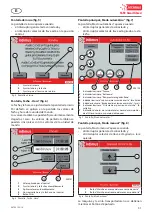
Pantalla de inicio (fig . 5)

La pantalla de inicio aparece cuando 

•  el interruptor general está conectado y 

•  el interruptor selector de llave está en la posición 

central.

1

3

2

000120

1

Ajustar el idioma

2

Ajustar la hora y la fecha

3

Ajustes para el técnico de servicio

fig. 5  Pantalla de inicio

Pantalla „Fecha - Hora“ (fig . 6)

La fecha y la hora se ajustan desde la pantalla de inicio.

Por defecto se aplican en la pantalla los valores de 

fecha y hora de la unidad de mando.

Los valores también se pueden fijar automáticamente.

Llegado el caso, los valores de pantalla también se 

pueden sincronizar con los valores de la unidad de 

mando.

1

2

3

4

5

000121

1

Valor aplicado por el control

2

Ajustar la hora y la fecha automáticamente

3

Aplicar valores automáticamente

4

Sincronizar la hora y la fecha con el control

5

Botón Atrás

fig. 6  Pantalla „Fecha - Hora“

Pantalla principal „Modo automático“ (fig . 7)

La pantalla „Modo automático“ aparece cuando 

•  el interruptor general está conectado y 

•  el interruptor selector de llave está girado a la de-

recha.

000122

1

2

3

4

5

6

7

1

Indicador luminoso "Avance"

2

Indicador luminoso "Retroceso"

3

Indicador luminoso "Recipiente recogedor lleno"

4

Indicador luminoso "Lubricar el mecanismo de corte" - facultativo

5

Indicador luminoso "Banda de alimentación en marcha" - facult.

6

Indicador luminoso "Sistema de aspiración en marcha" - fa-

cultativo

7

Indicación de horas de servicio totales, horas de servicio des-

de el último servicio y número de bloqueos

fig. 7  Pantalla „Modo automático“

Pantalla principal „Modo manual“ (fig . 8)

La pantalla „Modo manual“ aparece cuando 

•  el interruptor general está conectado y 

•  el interruptor selector de llave está girado a la iz-

quierda.

1

2

000123

1

Botón "Marcha en avance del mecanismo de corte"

2

Botón "Marcha en retroceso del mecanismo de corte"

fig. 8  Pantalla „Modo manual“

La máquina y la cinta transportadora no se detienen 

mientras el botón esté pulsado.

Содержание 16.50 SmartShred

Страница 1: ...16 50 SmartShred Betriebsanleitung D Operating Instructions GB Instructions d opération F Instrucciones de uso E 000210 94709 1 02 18 ...

Страница 2: ... 10 D Operating Instructions page 11 18 GB Instructions d opération page 19 26 F Instrucciones de uso página 27 35 E Typ Type Tipo Típus 655 10C 655 6C Vor der Inbetriebnahme die Betriebsanleitung durchlesen Before operating please read the Operating Instructions Veuillez lire le mode d emploi avant la mise en service Leer las instrucciones de uso antes de la puesta en servicio ...

Страница 3: ...sprechend dem vorgeschriebenen Verwendungszweck einge setzt werden Der Netzanschluss der Maschine muss frei zugängig sein Die Maschine nur in geschlossenen und temperierten 10 40 C Räumen einsetzen Das Gerät darf nicht von mehreren Perso nen gleichzeitig bedient werden Die Auslegung der Sicherheitselemente be ruhen auf einer gefahrlosen Bedienung im Einmannbetrieb Verletzungsgefahr Lose Teile von ...

Страница 4: ... werden mit Hilfe der mitgelie ferten Verbindungsbolzen und der Verschlusseinsätze zusammenmontiert Der Bolzen wird durch das anzu schraubende Teil gesteckt und so dem im anderen Teil befindlichen Verschlusseinsatz zugeführt Durch Dre hen des Verschlusseinsatzes im Uhrzeigersinn Pfeil richtung wird der Bolzen dort verriegelt Gehen Sie nun beim Zusammenbau des Auffangbe hälters wie folgt vor 1 Rück...

Страница 5: ... betragen Der Leitungsquerschnitt der Stromzuführung am Anschlussort muss so dimensioniert sein dass bei blockierter Maschine die Spannung um max 15 absinkt Blockierstrom der Maschine 6 x Nennstrom 3 3 Überprüfung der Laufrichtung 1 000212 1 Not Aus Leiste Abb 3 Not Aus Leiste 1 Not Aus Leiste Abb 3 am Shredder Tisch ent riegeln Leiste herausziehen und Hauptschalter Abb 4 2 einschalten Stellung 1 ...

Страница 6: ...r Start grün Nur im Automatikbetrieb Bei Betätigung dieses Tasters laufen das Schneid werk und dasTransportband des Shredders an und die Maschine kann beschickt werden 4 Drucktaster Reset gelb Nur im Automatikbetrieb Taster nach Anweisung durch das Display betäti gen 5 Drucktaster Stopp rot Nur im Automatikbetrieb Bei Betätigung dieses Tasters wird der Shredder abgeschaltet und das Schneidwerk mit...

Страница 7: ...eit und Datum mit Steuerung synchronisieren 5 Zurück Button Abb 6 Bildschirm Datum Uhrzeit Hauptbildschirm Automatikbetrieb Abb 7 Der Bildschirm Automatikbetrieb erscheint wenn Hauptschalter eingeschaltet Schlüsselwahlschalter nach rechts gedreht 000122 1 2 3 4 5 6 7 1 Leuchtanzeige Vorwärts 2 Leuchtanzeige Rückwärts 3 Leuchtanzeige Auffangbehälter voll 4 Leuchtanzeige Schneidwerk ölen fakultativ ...

Страница 8: ...schine selbst stehen Eine erhöhte Stehfläche z B durch Palet ten Kisten etc vor der Maschine ist bezüg lich der erforderlichen Sicherheitsabstände zum Schneidwerk nicht zulässig Führen Sie dem Shredder niemals mehr als die angegebene Höchstmenge Pa pier siehe Technische Daten auf Sei te 10 zu Sollte trotzdem einmal zuviel Papier in das Schneidwerk gelangt sein siehe Automa tik Schaltung bei Überfü...

Страница 9: ...GEFAHR Lebensgefahr durch Stromschlag Im Falle einer Reparatur vor dem Öffnen der Anlage den Netzstecker ziehen sowie den Hauptschalter ausschalten und mit einem Vorhängeschloss sichern HINWEIS Sollten betriebsbedingte Fehler auftreten er scheinen auf dem Display spezifische Popup Fenster mit der Fehlermeldung Darin erfahren Sie Fehlerursache und Maßnahmen zur Behe bung Lässt sich das Problem nich...

Страница 10: ...s oder einer Fettpresse mit einem handelsübli chen Schmierfett einfetten 3 Seitenabdeckung anmontieren und den Netzste cker einstecken Die Maschine kann wieder in Be trieb genommen werden 7 2 Tipp zur Energieeinsparung Achten Sie darauf dass die Maschine über Nacht aus geschaltet ist Hauptschalter Abb 4 2 in Stellung 0 7 3 Entsorgung der Maschine Entsorgen Sie die Maschine am Ende ihrer Le bensdau...

Страница 11: ...e montage Diagrama eléctrico 36 11 Certificate of Conformity 51 1 Safety Information DANGER Risk of injury The machine may only be used for its intended purpose The machine s mains connection must be freely accessible The machine should only be operated in closed rooms within a temperature range of 10 to 40 C The device may not be used by several people at the same time The safety elements design ...

Страница 12: ...king elements used to connect the back panel the two side panels and the base frame are included in delivery Insert the bolt through the panel you wish to connect and match it to the locking element on the other part Turning the lo cking element clockwise in the direction of the arrow secures the bolt To assemble the shredder bin proceed as follows 1 Connect the back panel to the base frame 2 Conn...

Страница 13: ...000212 1 Emergency stop rail fig 3 Emergency stop rail 1 Free the emergency stop rail pull out the rail fig 3 on the shredder feed table Switch on the main switch fig 4 2 i e to position 1 2 Turn the key selector switch fig 4 1 to the right The display appears 3 Press the green start button fig 4 3 4 Check that the shredder is running in the correct direction and correct the phase relation at the ...

Страница 14: ...s error messages NOTE To avoid display damages from scratches and cracks put tools and the like out of your hand before operating 4 2 Display Four main screens are used to control the machine NOTE The display contains various buttons fields and illuminated displays Circular illuminated information display Rectangular text output field Rectangular with 3D effect input button Start screen fig 5 The ...

Страница 15: ...ration screen The machine and conveyor belt will continue running for as long as the button is pressed 4 3 Emergency stop bar fig 3 1 Should it be necessary for any reason to switch off or stop the machine as quickly as possible this can be achieved by pressing the emergency stop bar To switch on again release the bar pull it out and opera te the green Start button fig 4 3 5 Operation 5 1 Operatin...

Страница 16: ...ling of the shredded mate rial possible and ensures a longer life of the cutting system 5 3 Automatic response in case of overloading CAUTION Risk of injury Never pull paper from the cutting mecha nism by hand when the machine is perfor ming an automatic feeding operation In case you accidentally overload the shredder it will automatically alleviate the problem as follows The cutting system become...

Страница 17: ...ugh the overheated motor has been allowed to cool down pop up window no longer closes there is a defect in the ma chine In this case please inform our customer service department 6 2 Fault checklist If the machine is not functioning properly you should check the following is the machine plugged into the mains power sup ply is the locking switch fig 4 1 unlocked is the main switch fig 4 2 turned on...

Страница 18: ...tion 7 2 Energy saving tip Be certain that the machine is turned off overnight main switch fig 4 2 switched to 0 7 3 Disposing of the machine Dispose of the machine in an environmentally sound fashion at the end of its useful service life Do not dispose of any of the parts inclu ded in the machine or its packaging with household trash 8 Accessories Description Order No Plastic bag 900 x 900 x 1500...

Страница 19: ...sécurité Danger Risque de blessure La machine ne doit être utilisée qu en conformité avec l usage pour lequel elle a été conçue Le branchement de la machine au secteur doit être librement accessible La machine ne doit être utilisée que dans des locaux fermés et tempérés 10 40 C La machine ne doit pas être utilisée par plusieurs personnes en même temps La conception des éléments de sécurité re pose...

Страница 20: ...eux parois latérales et les cadres supports doivent être montés à l aide des verrouillages de montage et des goujons de raccordement Il faut enfoncer le goujon dans la partie à visser puis ainsi introduit dans l autre partie du verrouillage En tournant le verrouillage dans le sens des aiguilles de montre dans le sens de la flèche le goujon sera blo qué Effectuer l ordre de montage du réceptacle co...

Страница 21: ...ge de la machine cou rant de blocage de la machine 6 x le courant no minal 3 3 Controle du sens de rotation 1 000212 1 Barre d arrêt d urgence fig 3 Barre d arrêt d urgence 1 Débloquer la barre d arrêt d urgence fig 3 de la table du destructeur tirer la barre et enclencher l interrupteur principal fig 4 2 position 1 2 Tourner la clé fig 4 1 vers la droite L écran apparaît 3 Appuyez sur le bouton d...

Страница 22: ...es autres informations sont saisies et don nées par le biais de l écran réglages commande messages de statut messages d erreur REMARQUE Pour éviter des dommages comme rayures et cassures sur le display veuillez bien poser tous outils avant la mise en service 4 2 Écran Quatre écrans principaux vous assistent pour la com mande de la machine REMARQUE L écran propose différents boutons champs et voyan...

Страница 23: ...e le bouton reste appuyé 4 3 Barre d arrêt d urgence fig 3 1 Une pression sur cette barre d arrêt d urgence permet d arrêter la machine si celle ci pour une raison quel conque doit être stoppée le plus rapidement possible Pour la remettre en marche déverrouiller la barre en la tirant en arrière et enfoncer le poussoir Avance mécanisme de coupe fig 4 3 5 Utilisation 5 1 Fonctionnement du destructeu...

Страница 24: ...re cyclage de la matière détruite et votre bloc de coupe durera plus longtemps 5 3 Fonctionnement automatique lors d une surcharge Attention Risque de blessure En mode automatique ne pas tirer le papier du bloc de coupe à la main Si le destructeur est en surcharge les opérations su ivantes s effectuent automatiquement 1 Blocage du bloc de coupe 2 Le bloc de coupe et la bande de transport sont mis ...

Страница 25: ...nce fig 3 est elle déver rouillée tirer la barre rouge située sur la table le récipient fig 9 3 est il repoussé en butée le récipient fig 9 3 est il plein Le récipient doit être vidé la trappe de commutation fig 1 récipient plein est il libre de mouvement En cas de besoin libérer le trappe le moteur a t il été en surcharge voir description au paragraphe Panne de mo teur p 25 l une des phases est e...

Страница 26: ...resser à votre distributeur pour toute commande d accessoires ou de pi èces de rechange 9 Caractéristiques tech niques intimus 16 50 SmartShred Largeurs de coupe 10 x 70 mm 6 x 50 mm Performances de coupe en deux empilements 10 x 70 mm 450 520 feuilles 70g m2 6 x 50 mm 300 330 feuilles 70g m2 Tensions de raccorde ment 400 V 50 Hz 415 V 50 Hz 200 V 50 Hz 230 V 50 Hz 220 V 60 Hz 200 V 60 Hz Fusible ...

Страница 27: ...icate of Conformity 51 1 Indicaciones de seguridad Peligro Riesgo de lesiones La máquina solamente debe ser empleada conforme a la finalidad prescrita El acceso a la conexión a la red de la máquina tiene que estar siempre libre La máquina sólo deberá emplearse en estancias cerradas y aclimatadas 10 40 C El aparato no debe ser operado por vari as personas al mismo tiempo La concepción de los elemen...

Страница 28: ...n con ayuda de los pernos de unión y suplementos de cierre adjuntados al suministro El perno se mete por la pieza a atornillar pasándose así al suplemento de cierre que se encuen tra en la otra pieza Girando el suplemento de cierre en el sentido de las agujas del reloj sentido de la flecha se bloquea allí el perno Proceder ahora como indicado a continuación para el montaje del recipiente de recogi...

Страница 29: ...corrien te en el lugar de conexión se tiene que dimensio nar de manera que en el caso de un bloqueo de la máquina la tensión baje en un 15 como máximo corriente de bloqueo de la máquina 6 x corrien te nominal 3 3 Verificación del sentido de giro 1 000212 1 Regleta de parada de emergencia fig 3 Regletadeparadadeemergencia 1 Desbloquear la regleta de parada de emergen cia fig 3 en la mesa de la dest...

Страница 30: ...ición 1 o 0 3 Pulsador de arranque verde Solo en el modo automático Al accionar este pulsador se pone en marcha el me canismo de corte así como la cinta transportadora de la destructora de datos y la máquina se puede cargar 4 Pulsador de reinicio amarillo Solo en el modo automático Accionar el pulsador siguiendo las instrucciones mostradas en pantalla 5 Pulsador de parada rojo Solo en el modo auto...

Страница 31: ...antalla Fecha Hora Pantalla principal Modo automático fig 7 La pantalla Modo automático aparece cuando el interruptor general está conectado y el interruptor selector de llave está girado a la de recha 000122 1 2 3 4 5 6 7 1 Indicador luminoso Avance 2 Indicador luminoso Retroceso 3 Indicador luminoso Recipiente recogedor lleno 4 Indicador luminoso Lubricar el mecanismo de corte facultativo 5 Indi...

Страница 32: ...ador no debe encontrarse en una posición más alta que la de la misma máquina Una posición más elevada p ej mediante pa letas cajas etc delante de la máquina no es admisible debido a las distancias de seguri dad necesarias hasta el mecanismo de corte Evitar en todo momento una ali mentación de la destructora de do cumentos con una cantidad de papel mayor que la máxima indicada ver Características t...

Страница 33: ...ionar 1 2 3 000125 1 Estribo 2 Recipiente de recogida 3 Pared delantera del recipiente fig 10 Vaciado del recipiente recogedor NOTA La máquina solo funciona si el recipiente re cogedor está insertado Para señalar que el recipiente no está in sertado la indicación Recipiente recogedor lleno se enciende y la máquina no se puede arrancar 5 6 Lubricador automático Véase la instruccón adjunta lubricado...

Страница 34: ...s funcionamientos erróneos no debe utilizarse la máquina En ese caso in forme a nuestro servicio de atención al cliente 7 Mantenimiento eliminación 7 1 Mantenimiento del mecanismo de transmisión Peligro Peligro de lesiones por descarga eléctri ca y piezas en movimiento Antes de abrir la carcasa desconectar la máquina por el interruptor general y extraer el enchufe de red NOTA No está permitido rea...

Страница 35: ...us 16 50 SmartShred Anchuras de corte 10 x 70 mm 6 x 50 mm Capacidad de corte en dos pilas 10 x 70 mm 450 520 hojas 70g m2 6 x 50 mm 300 330 hojas 70g m2 Tensión de conexión 400 V 50 Hz 415 V 50 Hz 200 V 50 Hz 230 V 50 Hz 220 V 60 Hz 200 V 60 Hz Fusibles previos Fusible gl clase de asignación 1 400 V 415 V 50 Hz 35 A 220 V 230 V 50 Hz 40 A 200 V 50 60 Hz 63 A Anchura de trabajo 500 mm Nivel de rui...

Страница 36: ...the contacts 19 20 as well as 24 10 are connected in the dummy plug a Schaltplan angepasst Jünger 11 05 2017 Main Switch 1 2 3 4 5 6 Q1 63A Hauptschalter L1 X1 L2 L3 PE U1 V1 W1 W2 U2 V2 PE M1 9 0 7 5kW M 3 1 2 K1M 11 0 32A 3 4 5 6 1 2 K2M 11 1 32A 3 4 5 6 X1 U1 V1 W1 W2 U2 V2 1 2 3 4 5 6 F1 9 2 23 32A 2 1 K4M 11 4 32A 4 3 6 5 2 1 K3M 11 3 18A 4 3 6 5 1 2 K5M 11 5 9A 3 4 5 6 1 2 3 4 5 6 F2 9 3 9 1...

Страница 37: ...main power 1 Änderung 0 7 6 Gepr Ersatz von 8 9 3 5 4 20 06 2017 Intimus International GmbH 4 2 Name 5 4 17 100 240VAC 24VDC 5A 24 28 8VDC U_Out ABL 8REM24050 TELEMECANIQUE a Schaltplan angepasst Jünger 11 05 2017 0V 0 230V 400 PE T1 100VA F1 X1 2A F2 2A F3 2A X1 PE F4 X1 4A T2 5A PE PE PE N L 0VDC 5 0 24VDC 5 0 PE 5 0 L1 3 9 L3 3 9 PE 3 9 230V 7 0 N 7 0 ...

Страница 38: ...lap DE E0 6 I6 DE E0 7 I7 8 8 Drehgeber rotary encoders COM2 DE E1 0 I8 DE E1 1 I9 14 3 Optional Schwimmerschalter Öler Optional float switch oiler DE E1 2 I10 Wicklungsschutz Presse optional Wicklungsschutz Abförderband DE E1 3 I11 9 0 Wicklungsschutz Shredder Winding protection Shredder DE E1 4 I12 DE E1 5 I13 15 4 Optional Wicklungsschutz Zuförderband Optional winding protection conveyor belt V...

Страница 39: ...2 33 34 TB2 34 K8 EXPANSION MODULE A1 TB1 A1 A2 TB1 A2 S33 TB1 S33 S34 TB1 S34 S11 TB1 S11 S12 TB1 S12 S22 TB1 S22 S42 TB1 S42 S21 TB1 S21 S41 TB1 S41 S39 TB1 S39 11 12 K1M 11 0 11 12 K2M 11 1 A1 A2 9A K11M 1 2 6 8 3 4 6 8 5 6 6 9 12 11 6 6 5 6 K11M 6 8 3 4 K11M 6 8 1 2 K11M 6 8 13 14 S6 Reset 11 12 K11M 6 8 27 X1 28 X1 29 X1 30 X1 11 12 S5 Schaltklappe switching flap 8 6 TB1 0 E4 6 9 2 Motorschut...

Страница 40: ...eis Control circuit 1 Änderung 0 7 6 Gepr Ersatz von 8 9 3 8 4 13 12 2017 Intimus International GmbH 7 2 Name 5 7 17 a Schaltplan angepasst Jünger 11 05 2017 X2 12 0 24 11 12 15 1 14 13 18 20 13 14 21 22 K6M 11 6 12A X1 47 48 49 50 51 52 53 54 A1 A2 K11 24V 14 11 7 1 11 14 K11 7 0 0VDC 6 9 0VDC 8 0 24VDC 6 9 24VDC 8 0 SIK 6 9 230V 4 9 230V 14 0 N 4 9 N 8 0 ...

Страница 41: ...th long discharge conveyor 13 14 23 24 S2 Schlüsselschalter key switch Automatik Aus Hand I0 DE A1 S2 14 Automatik Automatic E0 0 5 1 I1 DE S2 24 Hand Manually E0 1 5 1 I4 DE A1 S4 12 Stop E0 4 5 2 I3 DE S3 14 Start E0 3 5 1 11 12 S4 Stop 13 14 S3 Start BN BK BU B1 Drehgeber rotary encoders I7 DE B1 BK Drehgeber rotary encoders E0 7 5 3 I5 DE S8 14 Schaltklappe switching flap E0 5 5 2 13 14 S5 6 8...

Страница 42: ...flap baler E5 1 6 1 4 K15 14 Taster Vor Presse Button forward baler E5 2 6 1 5 K16 14 Taster Zurück Presse Button Back baler E5 3 6 1 6 K17 14 Taster Stop Presse Button stop baler E5 4 6 1 X1 9 X1 10 57 58 59 60 95 96 F2 3 6 9 13A 2 F2 96 Motorschutz Presse Motor protection baler E5 0 6 1 95 96 F1 3 2 23 32A 0 A3 F1 96 Motorschutz Shredder Motor protection shredder TB1 E4 6 6 1 7 A3 K18 14 Einfüll...

Страница 43: ...Intimus International GmbH 10 2 Name 5 10 17 a Schaltplan angepasst Jünger 11 05 2017 8 A3 K19 14 Stempel Hinten Presse Stamp Back baler TB1 E5 6 6 1 9 K20 14 Pressdruck erreicht Presse Press pressure reaches E5 7 6 1 10 K21 14 Ballen fertig Presse bales finished E6 0 6 1 X2 4 8 7 X1 62 63 64 A1 A2 K19 230V 14 11 10 1 A1 A2 K20 230V 14 11 10 2 A1 A2 K21 230V 14 11 10 3 11 14 K19 10 0 11 14 K20 10 ...

Страница 44: ...5 4 3 3 5 6 5 3 5 A1 A2 K4M 32A 2 1 3 4 4 3 3 4 6 5 3 4 A1 A2 K5M 9A 1 2 3 6 3 4 3 6 5 6 3 6 A1 A2 K6M 12A 13 14 21 22 7 3 X2 2 3 DA Q0 Shredder Vorwärts Shredder Forward A1 K1M A1 A0 0 5 2 DA Q1 Shredder Rückwärts Shredder Backwards K2M A1 A0 1 5 2 DA Q4 Stern Schütz Star contactor K3M A1 A0 4 5 3 DA Q5 Dreiecks Schütz Triangle contactor K4M A1 A0 5 5 3 DA Q8 Presse optional Abförderband Baler op...

Страница 45: ... 14 12 6 P K1 13 14 P S3 12 4 Stempel vor 13 14 P S1 12 4 Stempel zurück 11 12 P S10 12 3 Ausstoßklappe auf 11 12 P S14 12 3 Zweihand Bedienung 1 2 P M2 Ausstoßklappenöffner Motor M 1 P X1 14 P X1 15 16 17 18 19 X2 7 1 24 18 20 19 6 4 8 7 5 10 16 17 9 12 15 11 14 2 3 1 13 5 P X2 7 P X2 6 P X2 8 12 P X3 14 P X2 9 P X3 4 11 7 1 P X2 12 P X2 2 P X1 3 P X1 P X1 11 2 10 2 6 8 21 22 13 14 P S6 Öffnermot...

Страница 46: ...94709 1 02 18 46 16 50 SmartShred SB No 991 0416 4 a Seite page 11 U1 V1 W1 21 22 PE M4 Motor Abförderband Motor conveyor belt 3 M Θ X2 21 22 23 PE 19 20 24 10 ...

Страница 47: ... 15 4 20 06 2017 Intimus International GmbH 14 2 Name 5 14 17 a Schaltplan angepasst Jünger 11 05 2017 11 14 K22 14 5 X1 31 X1 32 1 2 M5 Öler oiler M 1 33 34 13 14 S7 Schwimmerschalter float switch I9 DE A1 S7 14 Optional Schwimmerschalter Öler Optional float switch oiler E1 1 5 3 DA Q7 Optional Öler Optional lubricator A1 K22 A1 A0 7 5 3 A1 A2 K22 14 11 14 1 230V 7 9 N 10 9 24VDC 10 9 0VDC 11 9 2...

Страница 48: ... 2017 Intimus International GmbH 15 2 Name 5 15 17 a Schaltplan angepasst Jünger 11 05 2017 U1 V1 W1 21 22 PE M6 Zuförderband feeding conveyor belt 3 M Θ X3 3 8 1 2 3 PE I13 DE A1 M6 21 Optional Wicklungsschutz Zuförderband Optional winding protection conveyor belt E1 5 5 4 X1 21 22 4 5 4 X3 5 5 TB2 Optional Zuförderband Optional feed conveyor A3 K10M A1 A2 3 6 3 A1 A2 K10M A1 A2 16 4 1 2 3 8 3 4 ...

Страница 49: ... Datum Optional Absaugung Optional suction Gepr 20 06 2017 Intimus International GmbH a Schaltplan angepasst Jünger 11 05 2017 U1 V1 W1 PE M7 Absaugung suction 3 M X4 3 7 L1 L2 L3 PE A1 A2 K10M A1 A2 15 6 1 2 3 8 3 4 3 8 5 6 3 8 4 TB2 Optional Absaugung Optional suction A3 K10M A1 A2 2 6 3 0VDC 15 9 ...

Страница 50: ... U4 V4 W4 27 28 29 30 31 32 33 34 35 36 37 38 39 40 41 42 43 44 45 46 47 48 49 50 51 52 53 54 55 56 57 58 59 60 61 62 63 64 65 66 F1 F2 F3 F4 Netzanschluss CEKON Power plug 3 phase M1 1 2 3 4 5 6 7 8 9 10 11 12 24 23 22 21 20 19 18 17 16 15 14 13 PE SW BN GR PE PE SW SW BN BN GR GR BN BL PE 21 22 23 24 11 12 15 1 14 13 18 20 10 19 5 9 16 17 6 4 8 7 2 3 X2 X1 B1 SW BN BL Drehzahlsensor rotation spe...

Страница 51: ...mmter gefährlicher Stoffe in Elektro und Elektronikgeräten Das vorgenannte Produkt entspricht folgenden harmonisierten bzw nationalen Normen We do hereby certify that the above mentioned product meets the requirements set forth in EEC Guidelines 2006 42 and EMC 2004 108 EEC including all changes and addendums to date thereto The object of the declaration described above is in confor mity with Dire...

Страница 52: ... Ernst Melchior Gasse 20 4 OG Top 6 1020 Wien 43 0 1 2583621 0 contact at intimus com Belgium intimus International Belgium NV Wayenborgstraat 22 2800 Mechelen 32 0 15 29 46 30 infobel intimus com Netherlands intimus International Netherlands B V Rivium Quadrant 2 6e verdieping 2909 LC Capelle aan den Ijssel 31 0 10 242 11 00 informatie intimus com Luxemburg intimus International Luxemburg S à r l...

Отзывы: