Intersil ISL6539 Скачать руководство пользователя страница 3

3

Operation

APPLY POWER

Prior to applying power, ensure that jumpers JP1 and JP5 
are in the desired position, all loads are connected properly, 
and all probes are connected properly. Jumpers JP3 and 
JP4 can be shunted and removed after power has been 
applied.

The V

IN

 power supply must be turned on or enabled first. 

Likewise, it must always be disabled or turned off last. This 
supply can be set from a minimum of 1.2V

DDQ 

to a 

maximum of 18V. After the V

IN

 power supply has been 

enabled, the VCC power supply may be enabled. The VCC 
power supply must be 5V.

The PGOOD status LED will give a visual indication of the 
V

DDQ

 regulator level. Table 3 describes the two states of the 

LED.

EXAMINE WAVEFORMS

Start-up is immediate following Power On Reset (POR). 
Using an oscilloscope or other laboratory equipment, the 
ramp-up and/or regulation of the outputs can be studied. 
Loading of the outputs can be accomplished through the use 
of electronic loads. Any other method, however, will work as 
well.

Evaluation Board Design

General

The evaluation board is built on a 2-ounce, four layer printed 
circuit board. The board is designed to support a continuous 
load of 5A on the V

DDQ

 rail and a simultaneous 3A 

continuous load on the V

TT

 rail while operating at room 

temperature and under natural convection cooling. Loading 
on V

REF

 should not exceed 10mA.

The schematic, bill of material, and the layout plots for the 
ISL6539EVAL1 evaluation board are provided at the end of 
this application note.

Eval Board Performance
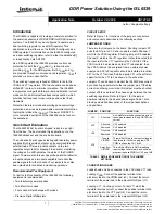
Power-Up

When the V

CC

 voltage exceeds the POR level, the ISL6539 

will begin the soft-start procedure. Figure 2 shows the start-
up of both the V

DDQ

 and V

TT

 rails from POR.

Figure 3 shows the start up the V

DDQ

 and V

TT

 rails through 

the enabling of the V

DDQ

 regulator.

LED

CONDITION

RESULT

CR1

Green

V

OUT1

 WITHIN PGOOD RANGE 

(89%-115% of nominal value)

Red

V

OUT1

 OUTSIDE PGOOD RANGE 

(89-115% of nominal value)

TABLE 3. PGOOD STATUS LED CONDITION INDICATOR

FIGURE 2. POR SOFT-START, VCC = VIN

FIGURE 3. ENABLED SOFT-START

Timebase: 500µs/DIV

V

DDQ

500mV/DIV

V

IN

1V/DIV

V

TT

500mV/DIV

Timebase: 500µs/DIV

V

DDQ

500mV/DIV

V

IN

1V/DIV

V

TT

500mV/DIV

V

EN

5V/DIV

Application Note 1278

Содержание ISL6539

Страница 1: ...the jumpers connectors and components described in the following sections JUMPER SETTINGS There are four jumpers on the board Shunting jumper JP3 pulls the EN1 pin to VCC and is used to enable Channel...

Страница 2: ...uld either be turned off or the outputs should be disabled VCC Power Connection Connect the positive terminal of a laboratory power supply to the VCC post J4 Connect the return terminal of the same lo...

Страница 3: ...well Evaluation Board Design General The evaluation board is built on a 2 ounce four layer printed circuit board The board is designed to support a continuous load of 5A on the VDDQ rail and a simult...

Страница 4: ...tors Transient Performance Figure 7 shows both the VDDQ and VTT rails while the VDDQ rail is under transient loading FIGURE 4 START UP INTO PREBIASED OUTPUT FIGURE 5 OUTUPT RIPPLE 90 PHASE SHIFT Timeb...

Страница 5: ...regulators These efficiencies were measured while the complementary regulator was disabled FIGURE 8 SOURCING TRANSIENT LOAD ON VTT FIGURE 9 SINKING TRANSIENT LOAD ON VTT Timebase 100 s DIV VDDQ AC Co...

Страница 6: ...o the ISL6539 datasheet for details on this The load capacity for either rail can be increased by exchanging the MOSFETs U2 and U3 for ones with higher current handling capabilities The ISEN resistor...

Страница 7: ...9 C10 R4 R5 C2 3 C1 VDDQ C6 VDDQ VTT VREF C23 C21 R9 C20 VCC VIN DDR BOOT1 UGATE1 PHASE1 ISEN1 LGATE1 VSEN1 OCSET2 OCSET1 SOFT1 BOOT2 UGATE2 PHASE2 ISEN2 LGATE2 VSEN2 PG2 REF SOFT2 PGOOD PG1 PGND1 PGN...

Страница 8: ...N SEMICONDUCTOR BAT54WT1 T 1 CR1 LED SMD 4P OTHER POLARIZED RED GRN LUMEX SSL LXA3025IGC TR 1 L1 PWR CHOKE COIL SMD 5 7mm 4 6 H 25 PANASONIC ETQ P6F4R6HFA 1 L2 PWR CHOKE COIL SMD 6x6x3mm 1 5 H 20 3 2A...

Страница 9: ...9 ISL6539EVAL1 Printed Circuit Board Layers ISL6539EVAL1 TOP SILK SCREEN ISL6539EVAL1 TOP LAYER Application Note 1278...

Страница 10: ...10 ISL6539EVAL1 INTERNAL 1 GROUND ISL6539EVAL1 INTERNAL 2 POWER ISL6539EVAL1 Printed Circuit Board Layers Continued VTT GND VDDQ VCC Application Note 1278...

Страница 11: ...ccordingly the reader is cautioned to verify that the Application Note or Technical Brief is current before proceeding For information regarding Intersil Corporation and its products see www intersil...

Отзывы: