


2
Loading V
TT
- Sinking Current:
To test V
TT
while the
regulator sinks current, connect the positive terminal of an
electronic load to the VDDQ post (J5). Connect the return
terminal of the same load to the VTT post (J6).
CAUTION: The return terminal of the load must float for this
to work properly.
CONNECTING PROBES
The table below lists all the locations available for
monitoring. The scope probe test points provide a low
impedance ground connection and all GND post can be
utilized as a ground connection for probes.
Terminals J12 (EN1) and J13 (EN2) may also be connected
to a pulse generator for controlled ON/OFF operation of the
respective regulators. However, make sure the signal
generator for the enable voltage is no more than 5V and that
the respective Enable jumper is removed.
CONNECTING POWER
Prior to connecting the power supplies to the evaluation
board, the power supplies should either be turned off or the
outputs should be disabled.
VCC Power Connection:
Connect the positive terminal of a
laboratory power supply to the VCC post (J4). Connect the
return terminal of the same load to the adjacent GND post
(J1).
V
IN
Power Connection:
Connect the positive terminal of a
laboratory power supply to the VIN post (J2). Connect the
return terminal of the same load to the adjacent GND post
(J3).
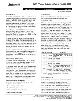
FIGURE 1. ISL6539EVAL1 BOARD
Power, Ground, Load,
and Probes.
Posts for connecting
Four Probe points
available for
ISL6539 IC
monitoring VTT,
VDDQ, and both
Phase nodes
Two locations for
monitoring Enable
signals
PGOOD status LED
Shorting this jumper
enables the VTT rail
Shorting this jumper
enables the VDDQ rail
This jumper can be used
to monitor bias current
to the ISL6539
90
o
Phase
Shift
No Phase
Shift
Phase Angle
Jumper Positions
Total Solution Area
TYPE
VOLTAGE
LOCATION
POST
V
DDQ
J5
V
TT
J6
V
PGOOD
J11
V
REF
J8
V
CC
J4
V
IN
J2
SCOPE PROBE
TEST POINT
V
TT
TP1
V
DDQ
TP2
V
PHASE1
TP4
V
PHASE2
TP3
TERMINAL
V
EN1
J12
V
EN2
J13
TABLE 2. PROBE TYPES AND LOCATIONS
Application Note 1278