background image

33 


Remote Display 


The 

iScan V90 can operate with two displays: one being 

designated as the 

Master (#1) and the other as the Remote 

(#2).   The transducer cables connect to the Master (#1) 

unit and the signal is automatically switched between the 

Master (#1) and the Remote(#2) during operation. 


The normal 

iScan V90 will operate as a stand-alone unit or 

as a 

Remote unit in a two display installation, but can not 

operate as a 

Master unit. 


The 

iScan V90 Remote Kit includes a 30’ Remote Cable 

(P/N 04-0014-009) that carries the sonar information from 

the transducer between the two displays.  It should be 

connected between the extra 9-pin connector on the rear of 

the 

Master(#1)  unit and the 9-pin GREEN input 

connector on the 

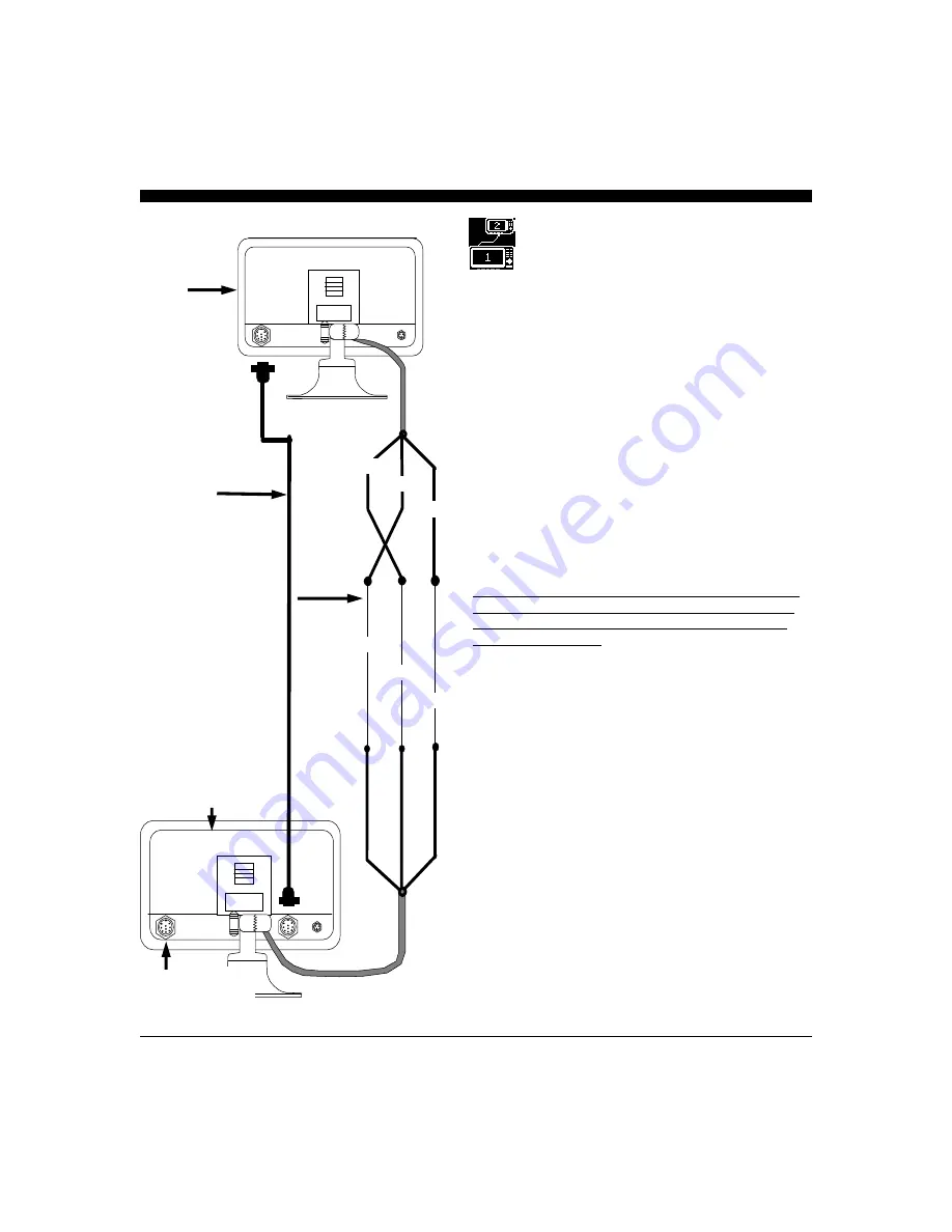
Remote (#2) unit.  In addition, the two 

units need to be connected via their serial ports with a three 

wire cable as shown on the sketch on the left.   


Note that the 

Orange wire from the Master (#1) connects 

to the 

Yellow wire from the Remote (#2) and the Yellow 

wire from the 

Master (#1) connects to the Orange wire 

from the 

Remote (#2).  The Green wires from both units 

are tied together.    


Once connected, you will need to go into the 

SETUP menu 

of each unit and set the standard unit up as a 

REMOTE

(#2) and the other unit unit (the one included with the 

REMOTE STATION KIT with two 9-pin connectors on 

the rear)  as the 

MASTER(#1) unit.  See page 19 for 

details. 


In a two-station system, the 

Master (#1) must always be 

turned on.  Then, if the 

Remote PWR button is pressed, 

the 

Master (#1) display will go into a standby mode while 

the 

Remote (#2)  is being used.  To re-activate the Master  

(#1) station, the Master Display PWR button needs to be 

briefly pressed. (pressing for more than a few seconds will 

turn the Master off).    


If the 

Master (#1) is turned off, for any reason, both 

displays will not function. 

Remote (2nd Station) Connections 

#2 

30’ Remote Cable 

# 04-0014-009 

TRANSDUCER 

(connects to  

Master Unit) 

#1 

GREEN 

GREEN 

YELLOW 

ORANGE 

ORANGE 

YELLOW 

Length of  

3-Conductor Wire 

REMOTE 

UNIT 

MASTER UNIT 

Содержание iScan V90

Страница 1: ...1...

Страница 2: ...ant to us To this end we welcome any comments or suggestions that you might have in regard to this equipment It is very important that you complete and return the WARRANTY REGISTRATION CARD within 15...

Страница 3: ...ducer Adjustments 21 Demo 21 System Reset_____________________________________________________________21 Displays 22 Vertical 22 Down 23 Down Zoom 23 Data 24 Operating Adjustments 25 Range 25 Gain 25...

Страница 4: ...can be fully protected Should you experience a problem with your iScan V90 first refer to the Troubleshooting section page 34 of this manual Most common problems and their solutions are described her...

Страница 5: ...irected in an almost unlimited number of directions For example using an 8 element phased array transducer the iScan V90 is capable of steering the acoustic beam in any of 60 different directions Sinc...

Страница 6: ...e so that it does not run parallel or close to the transducer cable engine refrigeration bilge pump or any other critical wiring An in line fuse holder is included with your unit and should be placed...

Страница 7: ...unting the mounting base portion of the Quick Disconnect Mount is removed To remove the mounting base loosen the thumb screw until it seperates from the upper portion of the Quick Disconnect Mount Whi...

Страница 8: ...Main Power I O Wiring Cable from Quick Disconnect Bracket WIRE COLOR DESCRIPTION FUNCTION BLACK GND COMMON POWER SUPPLY GND RED POWER 11 16 VDC POWER SUPPLY WHITE RXA GPS INPUT PORT GREEN RX TX GND S...

Страница 9: ...ternatley the transducer may be placed forward of the keel ahead of the lifting strap location This should not be ahead of 1 3 aft of where the bow meets the waterline On planing hulls the transducer...

Страница 10: ...FORMANCE MAY BE SERIOUSLY DEGRADED THIS ACTION WILL VOID YOUR WARRANTY If you need a longer length cable than comes with the transducer 30 then purchase the optional 30 extension cables Interphase Par...

Страница 11: ...ts that regularly exceed 35MPH 30 knots Boats that exceed 40MPH 35knots cannot use transom mounted transducers but instead must use thru hull transducers Special Note The kick up feature is designed a...

Страница 12: ...acer with the mounting holes of the mounting bracket and slide the axle in place through the spacer 5 Place one small stainless steel spacer against the transducer bracket 6 Slide two urethane spacers...

Страница 13: ...sducer so that it is perpendicular from side to side and make sure the rounded shaped area is pointed towards the front of the boat Mounting the Transducer to the Boat After you have selected the opti...

Страница 14: ...ration of the transducer can be minimized by keeping the transducer mounted away from the keel and by not mounting too far forward b On sailboats the transducer should be mounted where the acoustic be...

Страница 15: ...d rise angle at the transducer mounting location If the thru hull transducer were mounted directly to the hull the sound beam would be tilted off the vertical at the same angle as the dead rise Most t...

Страница 16: ...s sealant Carefully confirm that the transducer is aligned so that the round front end is pointed directly toward the front of the boat 7 Install and tighten the bronze hex nut allow for swelling in w...

Страница 17: ...ng the brightness The screen menu provides visual feedback on the adjustment and often allows further choices by pressing one of the 5 softkeys below the menu If no button is pressed for several secon...

Страница 18: ...P MENU where you can select languages change the display units select a boat icon customize the system gain settings adjust the NMEA baud rate set a transducer keel offset add a compensation for the t...

Страница 19: ...L GAIN range choose the boat icon configure the display as either a MASTER or REMOTE or press MORE to adjust the STC to minimize the effect of surface clutter To choose the boat icon and the MASTER 1...

Страница 20: ...not used to calculate the digital depth or sound an alarm If you are having problems with the digital depth or alarms because of excessive surface clutter you can increase or decrease the exclusion ra...

Страница 21: ...ate angle of the unwanted upward or downward slope on the display Then proceed to the TRANSDUCER adjustment menu as above and press the softkey buttons to adjust the Level L It is possible to adjust 1...

Страница 22: ...y should look similar to the unit shown at right The boat icon at the top left of the display represents the position of the vessel The horizontal line with the scale across the top of the display rep...

Страница 23: ...lay you can ZOOM into any 25 portion of the depth being displayed For example if the downlooking depth range is 100 feet then the ZOOM function can be used to look at any 25 of the depth like 10 to 35...

Страница 24: ...and Lat Lon coordinates in large digits on the left side of the display see drawing at right In order for the Color Twinscope to show the speed temperature and Lat Lon coordinates the unit must be con...

Страница 25: ...choices available for adjusting the iScan V90 s receiver GAIN Press the button below AUTO so that the word AUTO is shown with a red border if you would like the Color Twinscope to automatically adjus...

Страница 26: ...e CURSOR DATA BOX will display the approximate DEPTH and RANGE from the vessel to that location It is important to realize that the depth information in the CURSOR DATA BOX is the result of a calculat...

Страница 27: ...below the symbols in the ALARM MENU or the NAV or UP DOWN button Press the softkey button below the EXIT symbol to save the setting and exit or press the button below the CLEAR symbol to disable the A...

Страница 28: ...em in a full screen format on the iScan V90 s display If more than one camera or video input is required you can use a video switch to choose between several video signals Pressing the softkey button...

Страница 29: ...e position in relation to the vessel Because the LCD display is only showing the acoustic echoes that are returned to the transducer it can not show forward bottom conditions that are hidden from its...

Страница 30: ...ustic energy Some of the acoustic energy is contained in an area called the sidelobes In conventional downlooking depthsounders the sidelobes create little problem except to distort the size of the ac...

Страница 31: ...n V90 the View Cam and the Fish Cam The View Cam is splash proof and is ideal for mounting in engine rooms or to monitor deck areas The View Cam is designed to fit into a plastic thru hull and has a w...

Страница 32: ...nds out the following NMEA 0183 sentences with the digital depth data DPT DBT Software Upgrades You can download software updates to your PC from our website at www interphase tech com and then upload...

Страница 33: ...from the Master 1 connects to the Yellow wire from the Remote 2 and the Yellow wire from the Master 1 connects to the Orange wire from the Remote 2 The Green wires from both units are tied together O...

Страница 34: ...int 5 DO NOT allow any solvents i e gasoline acetone to come in contact with the transducer or head unit as these may dissolve the material Troubleshooting Tips PROBLEM POSSIBLE SOLUTION Unit will not...

Страница 35: ...all an alternator filter to smooth the alternator s output signal Interference may also be caused by radiation from other nearby equipment and can be detected by turning off all other equipment and ob...

Страница 36: ...ing Rates Automatically optimized for selected range Power Requirements 11 to 16 VDC less than 1 2Amp Operating Temperature 0 to 50 degrees C 32 to 122 degrees F NMEA 0183 Inputs GLL VTG MTW NMEA 0183...

Страница 37: ...ite 140 Soquel CA 95073 In addition to speed your repair please fill out the following tear this page out of the manual or photocopy it and tape it to your unit for our technicians to review A copy of...

Страница 38: ...38 Notes...

Страница 39: ...t to extreme conditions beyond control of the manufacturer and Interphase Due to these conditions the warranty on these components is limited to one year against defects in workmanship or materials Th...

Страница 40: ...40 2880 Research Park Dr Suite 140 Soquel CA 95073 PHONE 831 477 4944 FAX 831 462 7444 comments interphase tech com www interphase tech com...

Отзывы: