Intellisense Systems Inc.
Page 10
– Rev 02.25.21
Micro Weather Station (MWS
®
) User Guide – Commercial Series
OPTIONAL SETTINGS AND ADVANCED FEATURES
Optional Settings
The optional settings control certain aspects of measurement timing and sampled parameters. They are stored
in memory and will stay in the last user-defined setting upon power-up.
GPS:
GPS latitude and longitude can be enabled or disabled by the user. GPS is enabled from the
factory by default, which will allow you to determine the unit’s location when reporting. If the location is
not desired, it can be disabled. However, a GPS lock is still required upon powerup to obtain elevation
and to obtain the proper system time for reported weather readings. GPS coordinates are reset upon
each power cycle (via the physical power switch) and a re-lock is required upon each new power-up.
GPS will also attempt a re-sync approximately once every 10 days of continuous operation to
accomodate for station movement and to update the system clock.
Image Requests (C500/600 models only):
A single image set can be requested or scheduled based on
system time (with hourly images being the fastest). When hourly images are requested, they will always
send at 56 minutes after the hour. The default setting is no images.
Ceilometer (C600 models only):
There are 3 ceilometer settings: “Disabled.” “Enabled,” and “Enabled
Always.” The “Enabled Always” command enables users to take 4 ceilometer readings (in 15-minute
intervals) regardless of what reporting mode the station is in, which may consume more power. The
“Enabled” setting changes the number of ceilometer readings depending on reporting mode. The default
setting is “Enabled.”
Raw Output Over Serial Connection
For advanced users or those using custom data processing
software, the station output can also be viewed over serial
USB connection in its raw format by plugging a MWS Power
and Data Cable into the “DATA” port on the unit and plugging
the receiving end into a standard USB Type-A port on your
PC. The station will output over serial automatically at each
sample time as defined in the reporting descriptions above.
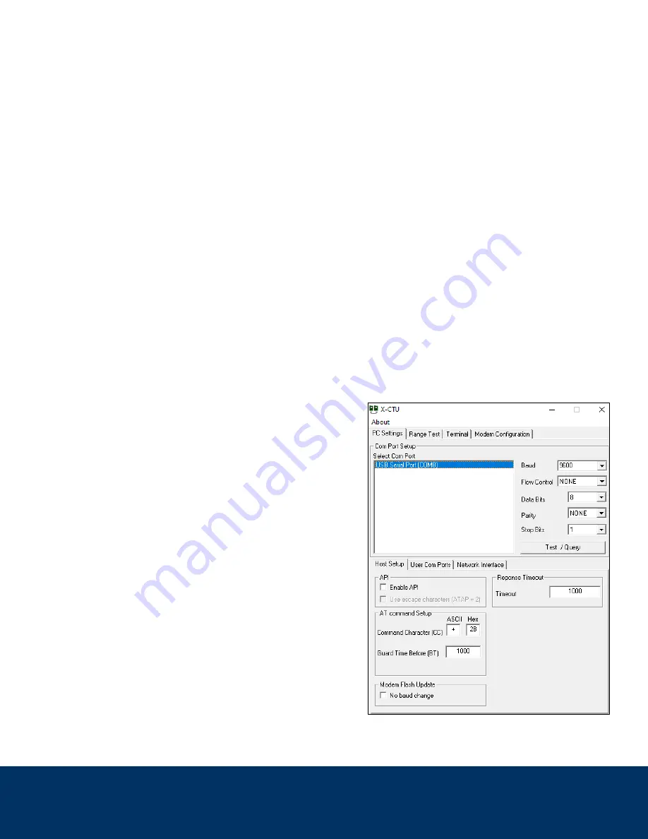
Output can be viewed on X-CTU or a similar serial terminal
software with the settings shown below and COM port that
coincides with the cable input. An example is pictured right:


