A-1
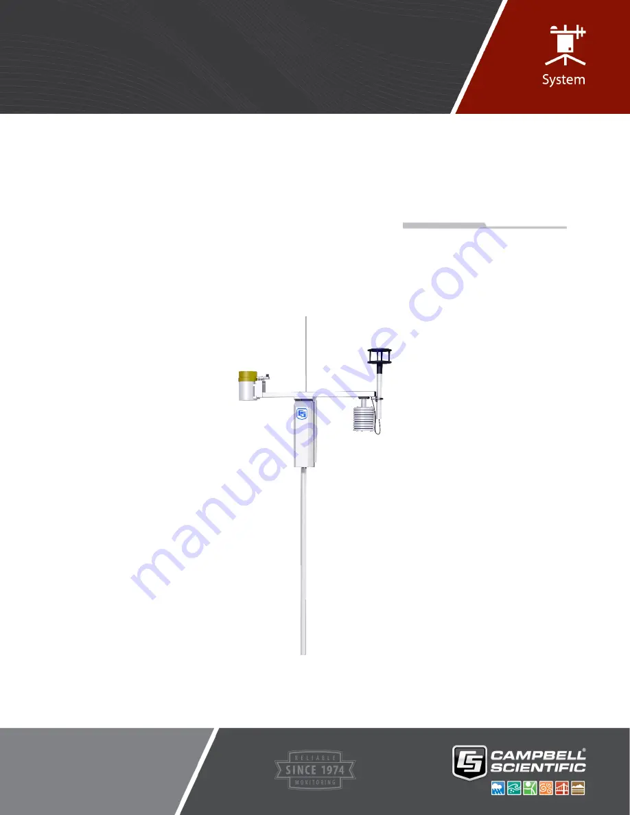
ET107
Weather Station
Revision: 12/18
Copyright © 1993 – 2018
Campbell Scientific, Inc.
Product Manual
Страница 1: ...A 1 ET107 Weather Station Revision 12 18 Copyright 1993 2018 Campbell Scientific Inc Product Manual...
Страница 2: ...ucts to CSI CSI will return such Products by surface carrier prepaid within the continental United States of America To all other locations CSI will return such Products best way CIP port of entry per...
Страница 3: ...ing address is CAMPBELL SCIENTIFIC INC RMA _____ 815 West 1800 North Logan Utah 84321 1784 For all returns the customer must fill out a Statement of Product Cleanliness and Decontamination form and co...
Страница 4: ...beginning work Wear a hardhat and eye protection and take other appropriate safety precautions while working on or around tripods and towers Do not climb tripods or towers at any time and prohibit cl...
Страница 5: ...ndation 8 5 2 2 Base Foundation Installation Procedure 8 5 2 3 AC Power Installation Procedure 10 5 3 Pole 11 5 3 1 Supplied Components for Pole Installation 11 5 3 2 Pole Installation Procedure 12 5...
Страница 6: ...the Cellular Modem 46 5 6 5 5 External Installation of a Cellular Modem 48 5 6 6 NL241 Wi Fi Accessory Kit 49 5 6 6 1 Antenna 49 5 6 6 2 Power Considerations 49 5 6 6 3 Internal Installation of Wi Fi...
Страница 7: ...or top layer 3 3 4 ET107 bottom layer 3 4 1 ET107 pole installation with currently available AC power option 5 5 1 Effect of structure on wind flow 7 5 2 ET107 pole base installation 8 5 3 Cut away vi...
Страница 8: ...power supply not shown 47 5 40 Wi Fi modem mounted inside the ET107 49 5 41 Lightning rod bracket installation 51 5 42 Grounding to lightning rod clamp 51 5 43 Solar panel mounting and cabling 52 5 4...
Страница 9: ...and brackets on ET107 pole C 4 C 6 Top clamp hook side up C 5 C 7 Enclosure mounted on ET107 pole C 6 C 8 Enclosure locking mechanism C 7 C 9 Fully mounted solar panel C 8 C 10 Procedure for installin...
Страница 10: ...d cleaning Leave the 034B wind vane in the protective cardboard sleeve until it s ready to be installed Ensure to remove the yellow cap from the RH and temperature sensor the red or green cap from the...
Страница 11: ...e edge of the lower flap first FIGURE 3 1 FIGURE 3 1 Cut flap packing tape 5 Cut the tape around the remaining flaps ensuring to only cut one layer deep 6 Lift up the cardboard flaps exposing the top...
Страница 12: ...3 3 ET107 with the Met One 034B ETM Wind Sensor top layer FIGURE 3 4 ET107 bottom layer Wind Set Enclosure Crossarm with Rain Solar and Temp RH Sensors Instruction Manual Cardboard Containing Wind Va...
Страница 13: ...le slide the enclosure to the top of the pole and secure it with the correct orientation Section 5 4 Enclosure p 14 5 Install the crossarm and sensors Section 5 5 Crossarm and Sensor p 15 4 3 User Sup...
Страница 14: ...nd wrenches 3 8 in 7 16 in 1 2 in 9 16 in 15 16 in Socket wrench and 7 16 inch deep well socket Adjustable wrench Pliers Conduit and associated tools as required Felt tipped marking pen Claw hammer Pi...
Страница 15: ...nd mounting kit with hangar if not using ac power Appendix C PS24 24 Ah Power Supply and 10 x 12 inch Enclosure p C 1 5 Installation 5 1 Siting and Exposure Do not install near power lines If any part...
Страница 16: ...large paved areas Sensors should be protected from thermal radiation and adequately ventilated Situations to avoid include large industrial heat sources rooftops steep slopes sheltered hollows high ve...
Страница 17: ...Supplied Components for Base Foundation The following components included with the ET107 are used to install the base 3 5 8 inch anchor L bolts 9 5 8 inch nuts 1 anchor template 5 2 2 Base Foundation...
Страница 18: ...o the form drive four stakes into the soil Secure the leveled form to the stakes with the 8p nails 7 Cap the ends of the conduit with duct tape 8 Position the conduit then wire into place by securing...
Страница 19: ...he transformer remotely and burying a low voltage line to the station The low voltage will carry up to 500 feet on an 18 AWG power cable 2 Shut off 110 Vac power at the main breaker 3 Connect the prim...
Страница 20: ...section tapered 1 lower pole section 6 5 8 inch washers 1 12 ft 10 AWG ground cable 1 white pole cap 1 20 ft communications cable phone or short haul modem 1 20 ft power cable for AC option only 1 sta...
Страница 21: ...the duct tape from both ends of the conduit 4 Remove the template 5 Slide the bottom and top half of the pole pieces together 6 Follow the ET Station Pole Assembly Instructions https s campbellsci co...
Страница 22: ...is established lock the leveling nut in place by tightening the lowest nut against it 16 Tighten the three top nuts with the wrench 5 3 3 Pole Grounding 5 3 3 1 Supplied Components for Pole Grounding...
Страница 23: ...communications devices and data retrieval peripherals are mounted in the ET107 enclosure 5 4 1 Enclosure Installation Mount the enclosure on the pole as shown in FIGURE 5 7 1 Remove the front lid 2 R...
Страница 24: ...ng above pole 5 5 Crossarm and Sensor Refer to Appendix D 2 Crossarm Exploded View p D 2 for a labeled exploded view of the crossarm 5 5 1 Supplied Components for Crossarm and Sensor Installation 1 ET...
Страница 25: ...arm needs to be installed after the enclosure is mounted on the pole You may need to temporarily remove the communications option Mount the crossarm as shown in FIGURE 5 9 without the wind sensor atta...
Страница 26: ...r holes in the top of the enclosure 4 Attach the arm to the enclosure by inserting and tightening four Phillips head screws FIGURE 5 9 5 Adjust the position of the enclosure so that the crossarm is or...
Страница 27: ...protective cap FIGURE 5 11 Temperature relative humidity sensor without yellow protective cap 3 Insert the temperature relative humidity into the radiation shield until it stops Adapter Temperature a...
Страница 28: ...losure Ensure that the plug is completely seated on the connector and the locking ring is turned a quarter revolution clockwise 5 5 4 034B Wind Sensor Wind Sensor Option MW Do the following to install...
Страница 29: ...at this time 4 Insert the mounting shaft through the U bolt on the crossarm 5 Adjust the mounting shaft so that the cable and connector coming out the end of the crossarm can plug easily into the mati...
Страница 30: ...nclosure Ensure that the plug is completely seated on the connector and the locking ring is turned a quarter revolution clockwise Plugging this sensor into the SDI 12 connector can damage this sensor...
Страница 31: ...tation 22 FIGURE 5 14 Screws that secure the electronics cover 4 Remove the electronics cover to expose the printed circuit board PCB FIGURE 5 15 FIGURE 5 15 Removal of the electronics cover Loosen Sc...
Страница 32: ...n screws 8 Reattach the ribbon cable to the CS I O port 9 Replace enclosure cover 5 5 5 2 WindSonic Attachment to Crossarm 1 Remove the three Phillips screws from the end of the white mounting shaft 2...
Страница 33: ...aft 4 Slide the connector and cable up through the center of the mounting shaft 5 Plug the cable into the sensor The connector has a key and needs to be pushed in then rotated clockwise to lock it in...
Страница 34: ...d tighten down the U bolt 10 Plug the cable into the Temp Sonic connector on the enclosure Ensure that the plug is completely seated on the connector and the locking ring is turned a quarter revolutio...
Страница 35: ...e plug is completely seated on the connector and the locking ring is turned a quarter revolution clockwise 5 5 7 Pyranometer 1 Adjust the three leveling screws until the bubble level indicates plumb F...
Страница 36: ...a quarter revolution clockwise 5 5 9 CS616 LC Water Content Sensor Optional The cable is waterproof but not armored Therefore Campbell Scientific recommends routing the cable through conduit especial...
Страница 37: ...rter revolution clockwise 5 5 11 Sensor Connections Each sensor cable plug attaches to a unique bulkhead connector FIGURE 5 4 and FIGURE 5 22 The labeling of the sensor cables match the labeling on th...
Страница 38: ...0 or LoggerNet a The station can be accessed directly using a CR1000KD keypad display at the weather station Plug the keypad into the extra plug coming off the 9 pin CS I O connector b A laptop can be...
Страница 39: ...RS 232 Port Autobaud 300 to 115 200 bps ME Autobaud SDC7 or SDC8 115 200 bps 5 6 1 Direct Connect to ET107 Station The ET107 station does not require an interface device for direct RS 232 communicatio...
Страница 40: ...dem at your computer over a dedicated phone line Phone line surge protection is built into the enclosure By default the COM220 phone modem is configured for SDC7 Connects with phone modem s RJ 11 patc...
Страница 41: ...Wire Use the following procedure to install the phone modem FIGURE 5 24 FIGURE 5 24 Phone modem mounting and connections battery not shown 1 Attach the modem to the modem bracket with the two screws...
Страница 42: ...n between a datalogger and computer over two twisted pairs of wires The maximum distance between modems is determined by baud rate and wire gage At 9600 bps the approximate maximum cable length is 6 0...
Страница 43: ...o the internal enclosure CS I O port with the ribbon cable supplied with the enclosure FIGURE 5 25 5 Wire the Rad modem to the enclosure with the 12 inch patch cable Match wire labels to wiring panel...
Страница 44: ...n F 02P22BPN Phone 847 677 2600 Components of the short haul kit used for external connections at the computer are 1 Rad Modem 1 5 ft 4 wire Patch Cable 1 10 ft 14 AWG Ground Wire 1 Surge Protector an...
Страница 45: ...and most radios offered by Campbell Scientific AC power is recommended when using radios with the station A 10 watt solar panel can be used but days without sunlight and winter months with little sun...
Страница 46: ...with a 10 watt panel would need at least one hour of sunlight every day to keep the battery charged 5 6 4 2 Internal Installation of the Radio If the ET107 was ordered with a radio kit skip this secti...
Страница 47: ...4 3 External Installation of the Radio The antenna should have been ordered with the radio kit The following components are provided with the radio kit for antenna installation on the ET107 pole 1 ant...
Страница 48: ...crossarm 2 Remove the cap off of the BNC bulkhead connector located on the lower left corner of the enclosure back 3 Attach the antenna cable to the BNC connector 4 Gently bring the cable up alongsid...
Страница 49: ...a should not be higher than the top of the lightning rod a Slide the U bolt behind the pole and through the oval notches on the adjustable angle mounting bracket FIGURE 5 31 FIGURE 5 31 Slide antenna...
Страница 50: ...Installation of the omnidirectional antenna is similar FIGURE 5 36 Mounting hardware that comes in the box with the Yagi antenna will not be used a Slide the back of the Yagi antenna into the saddle...
Страница 51: ...a 90 bend by the BNC connector end of the cable Take the cover off when you re done f Use one of the black wire ties to strap the antenna cable to the bundle of sensor cables g Tighten up the wire tie...
Страница 52: ...ie antenna cable to Yagi antenna and to pole j Wire tie the antenna cable to the pole FIGURE 5 36 Wire tie locations for omnidirectional antenna installation k Clean up the wire ties and put the cable...
Страница 53: ...GURE 5 38 To comply with the FCC RF exposure requirements the radio may be used only with approved antennas that have been tested with this radio and a minimum separation distance of 8 inches 20 cm mu...
Страница 54: ...rous cellular networks The networking and carrier used by the cell modem are determined by the active SIM card s inserted into the device Before purchasing a digital cellular modem ensure that the dat...
Страница 55: ...dem To use a cellular modem you must first establish cellular service The modem then needs to be activated and programmed for use with Campbell Scientific equipment Procedures for doing these tasks ar...
Страница 56: ...closure 4 Make sure all connections are tight 5 Use the null modem cable to connect the cellular modem s serial port to the ET107 RS 232 9 pin port FIGURE 5 39 6 Attach the power cable to the cellular...
Страница 57: ...enna firmly in place Do NOT over tighten the nuts on the saddle bracket or you might damage the antenna 3 If using the Yagi antenna aim the antenna at the cellular pole You may have to flip the adjust...
Страница 58: ...Enclosure p C 1 for mounting options and information on the PS24 5 6 6 3 Internal Installation of Wi Fi Modem If the wireless network link kit was ordered with the ET107 skip this section and go direc...
Страница 59: ...t and tighten its nuts to hold the antenna firmly in place Do NOT over tighten the nuts on the saddle bracket or you might damage the antenna 3 Adjust the antenna cable at the BNC connector so the cab...
Страница 60: ...top of the pole FIGURE 5 41 Position the clamp so it won t interfere with the connector cover FIGURE 5 41 Lightning rod bracket installation 2 Strip 2 54 cm 1 in from the top of the main green 10 AWG...
Страница 61: ...ould face the clamping screw 8 Tighten the screw to hold the rod firmly in place 5 8 Solar Panel Installation FIGURE 5 43 Solar panel mounting and cabling 1 Mount the solar panel to the pole using the...
Страница 62: ...ar panel shows tilt angle 3 After determining the tilt angle loosen the two bolts that attach the mounting bracket to the panel 4 Adjust the angle and tighten the bolts 5 Secure the wire to the mast u...
Страница 63: ...4 Plug the battery wire into the connector 5 Put the cover back on the PS150 and latch it in place Do not switch the power supply ON until ac or solar power has been connected to the back of the encl...
Страница 64: ...Sealing Desiccating Enclosure 5 10 1 Restraining Cables 1 Loosely wire tie power communication and grounding cable to the wire tie harness at the top of the back of the station FIGURE 5 47 Do NOT clip...
Страница 65: ...ire ties holding the cables to the wire tie harness and clip off excess ties FIGURE 5 48 5 10 2 Sealing and Desiccating the Enclosure The ET107 enclosure is supplied with two desiccant packs The desic...
Страница 66: ...omes with a default program and typically does not require additional programming Appendix E Default Programs p E 1 A variety of different software packages are available to work with the ET107 statio...
Страница 67: ...of the ET107 components is essential to obtain accurate data Equipment must be in good operating condition which requires a program of regular inspection and maintenance Routine and simple maintenanc...
Страница 68: ...manual for more information Perform sensor maintenance at regular intervals depending on the desired accuracy and the conditions of use A suggested maintenance schedule is outlined below Appendix B E...
Страница 69: ...onstant high winds blowing dust and or salt spray contamination Return the sensor to Campbell Scientific for bearing and reed switch replacement see Assistance page 1 year Replace the wind speed anemo...
Страница 70: ...d the solar radiation sensor pyranometer to Campbell Scientific for calibration refer to the Assistance page Sensor cannot be calibrated in the field Some users recommend calibrating this sensor on a...
Страница 71: ...e is displayed in the status table A new battery will have approximately 3 6 volts The CR1000 Status Table has a Lithium Battery field This field shows lithium battery voltage Send the ET107 enclosure...
Страница 72: ...y switching the PS150 power supply to OFF then to ON or by disconnecting and reconnecting the battery plug The keypad should power up and the Campbell Scientific logo and text should appear on the dis...
Страница 73: ...n place see FIGURE 5 22 3 Check connectors for any corrosion on pins 4 If Short Cut or VisualWeather is used to create the station program double check the wiring diagram to see if it matches the phys...
Страница 74: ...good samples is less than 98 of the expected samples the WindSonic may be in need of repair TABLE 6 2 WindSonic Diagnostic Codes Diagnostic Status Comment 0 Okay All okay 1 Axis 1 Failed Insufficient...
Страница 75: ...ET107 Weather Station 66 FIGURE 6 2 Schematic of HMP60 ETS RH and Temperature Probe and connector Temp RH FIGURE 6 3 Schematic of 034B ET Wind Speed and Direction Probe and connector WS WD...
Страница 76: ...Station 67 FIGURE 6 4 Schematic of WindSonic1 ET Wind Sensor soil temperature sensor 107 LC or 108 LC and connector Temp Sonic FIGURE 6 5 Schematic of CS305 ET Solar Radiation Sensor and connector So...
Страница 77: ...ar Radiation Sensor with OHM readings of 450 to 650 FIGURE 6 6 Schematic of TE525 ET Rain Sensor and connector Rain Precip FIGURE 6 7 Schematic of 107 LC or 108 LC Temperature Sensor or CS616 LC Soil...
Страница 78: ...2 Power Schematics 18 to 24 VRMS or 15 to 40 Vdc Solar Panel Power Solar Panel Solar Panel PS150 Charger Regulator Charge Charge Power Note PS150 Charger Regulator is not sensitive to polarity AC Red...
Страница 79: ...ET107 Weather Station 70 6 3 3 Communication Modems Schematics FIGURE 6 10 Schematic of short haul or phone modem and connector COMM...
Страница 80: ...magnetic declination is the number of degrees between True North and Magnetic North Magnetic declination for a specific site can be obtained from a USGS map local airport or through a NOAA web calcula...
Страница 81: ...ed to 0 degrees to get True North as shown in FIGURE A 3 For example the declination for Longmont CO 10 June 2006 is 9 67 thus True North is 360 9 67 or 350 33 as read on a compass Likewise the declin...
Страница 82: ...latitude and longitude You can look up your site s latitude and longitude by entering the Zip Code or the Country and City and then clicking the Get Add Lat Lon button FIGURE A 4 Click the Calculate b...
Страница 83: ...Appendix A Determining True North and Wind Sensor Orientation A 4 FIGURE A 5 NOAA calculated declination using HTML result format...
Страница 84: ...ndix B ET107 Maintenance Log Station Installation Date ___________________ CLEAN INSPECT RAIN GAGE SENSOR Recommended Weekly CLEAN INSPECT RAIN GAGE SENSOR Recommended Weekly Date OK Comments Date OK...
Страница 85: ...ended Quarterly Date OK Comments REPLACE WIND SPEED BEARINGS AND REED SWITCH Recommended Yearly Date OK Comments REPLACE RH CHIP IN THE HMP60 ETS TEMP RH SENSOR Recommended Yearly Date OK Comments REP...
Страница 86: ...10 inch by 12 inch environmental enclosure FIGURE C 1 through FIGURE C 3 Typically the PS24 is ordered without a charging regulator and the PS100 or PS150 is moved from the station enclosure to the PS...
Страница 87: ...Appendix C PS24 24 Ah Power Supply and 10 x 12 inch Enclosure C 2 FIGURE C 2 24 Ah battery and battery cable FIGURE C 3 Enclosure supply kit...
Страница 88: ...til instructed to do so 1 Place the top enclosure bracket on the pole at approximately 40 inches above the bottom of the pole The bracket should be installed with the hook side up and facing north 2 S...
Страница 89: ...inches below the top clamp This clamp is installed with the hook side down The bracket might have to be moved a little to accept the enclosure bracketing so don t tighten the bracket yet FIGURE C 5 sh...
Страница 90: ...Appendix C PS24 24 Ah Power Supply and 10 x 12 inch Enclosure C 5 4 Hook the enclosure on the top bracket as shown in FIGURE C 6 FIGURE C 6 Top clamp hook side up...
Страница 91: ...sure bracket should slide between the top lip of the bottom strut mount bracket and the notch directly below Move the bottom bracket if necessary then bolt the bottom bracket down see FIGURE C 7 Do NO...
Страница 92: ...l Phillips screw underneath the mechanism and slide it to the left Once in place put a small wire tie in the hole to the right of the locking mechanism see FIGURE C 8 To remove the enclosure from the...
Страница 93: ...sure into the conduit at the bottom of the 10 inch by 12 inch enclosure Leave a loop of all cables under the 10 inch by 12 inch enclosure to act as a drip line Cut both cables to whatever length you n...
Страница 94: ...Connect one wire per CHG terminal block 12 If the charging source is a solar panel remove the blanket or box from the solar panel once it s wired into the CH150 PS100 or PS150 regulator The charging...
Страница 95: ...the ET107 station enclosure has a two pin connector on one end and tinned wires on the other 13 Toggle the power switch on the regulator CH100 PS100 CH150 or PS150 to the OFF position 14 Wire the powe...
Страница 96: ...of the POWER connector to the ground connector on the gray terminal strip and the red wire to the 12V connector on the terminal strip The wire and plug previously used with the PS100 or PS150 can be...
Страница 97: ...D 1 Appendix D Exploded Views D 1 Enclosure Exploded View...
Страница 98: ...Appendix D Exploded Views D 2 D 2 Crossarm Exploded View...
Страница 99: ...lic Rain24Ttl Alias Rain 1 RainHrTtl CONNECTOR TEMP RH HMP60 ET Public AirTempC Public AirTempF Public RelHum CONNECTOR Solar Radiation Public SlrRad_W Miscellaneous variables and calculations Public...
Страница 100: ...FieldNames no_data_TOT EndTable BeginProg Set all rain variables to zero For n 1 To 24 Rain n 0 Next n one 1 SerialOpen Com1 38400 3 0 432 Scan 5 Sec 3 0 BattVolt Status Battery 1 1 LogrTmpC Status Pa...
Страница 101: ...Then WindChilC WC_AirtempF If WC_AirtempF 50 OR WindSpd_mph 3 Then WindChilC AirTempF WindChilC 5 9 WindChilC 32 Heat Index calculation If AirTempF 80 AND RelHum 40 Then HeatIndxC 42 379 2 04901523 Ai...
Страница 102: ...ge 1 SlrRad_W FP2 0 Maximum 1 SlrRad_W FP2 0 False Maximum 1 DewPntC FP2 False False Minimum 1 DewPntC FP2 False False Maximum 1 WindChilC FP2 False False Minimum 1 WindChilC FP2 False False Maximum 1...
Страница 103: ...10 Then WC_WSmph 110 Trap and set any airtempF less than 50 WC_AirtempF AirTempF If WC_AirtempF 50 Then WC_AirtempF 50 WindChilC 35 74 0 6215 WC_AirtempF 35 75 WindSpd_mph 0 16 0 4275 WC_AirtempF _ Wi...
Страница 104: ...ansformer The transformer should be mounted inside a user supplied junction box according to local electrical codes Dangerous electrical accidents may be avoided by locating the transformer remotely a...
Страница 105: ...incoming two conductor cable to the power cable provided with the station Use the direct burial splice kit when splices are in a valve box or buried 6 Connect the power plug to the Power connector on...
Страница 106: ...Asia Location Bangkok Thailand Email info campbellsci asia Website www campbellsci asia China Location Beijing P R China Email info campbellsci com cn Website www campbellsci com cn Spain Location Ba...