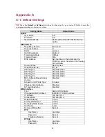
Service
Name
servicename
LAN Interface
Method of obtaining an IP Address Set manually
IP
Address
192.168.0.1
Subnet
Mask
255.255.255.0
Default
Gateway
0.0.0.0
DHCP Server
Functionality
Enabled
Default
Gateway
192.168.0.1
Subnet
Mask
255.255.255.0
Primary
DNS
Server
192.168.0.1
Secondary DNS Server
0.0.0.0
First Allocateable IP Address
192.168.0.2
Allocateable IP Address Count
20
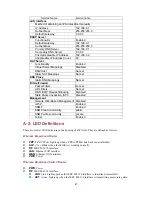
NAT Server
Functionality
Enabled
Virtual Server Mappings
Disabled
DMZ Host
Not set
Static NAT Mappings
Not set
DNS Proxy
Static DNS Mappings
Not set
Filters/Firewall
Packet Filters
Not set
URL Filters
Not set
WAN ICMP Request Blocking
Disabled
State Packet Inspection (SPI)
Disabled
Management
Remote Web-Based Management Disabled
UPnP
Enabled
SNMP
Enabled
SNMP read community
public
SNMP
write
community
private
Telnet
Enabled
A-2: LED Definitions
There are several LED indicators on the housing of a WIASA. They are defined as follows:
Wireless Broadband Router
PPP
:
PPP/PPPoE
. Lights up when a PPP or PPPoE link has been established.
ALV
:
Alive
. Blinks when the WIASA is working normally.
RF
:
IEEE 802.11b interface
LAN
:
Ethernet LAN interface
WAN
:
Ethernet WAN interface
PWR
:
Power
Wireless Broadband Switch Router
PWR
:
Power
RF
:
IEEE 802.11b interface
LNK
:
Link
. Lights up when the IEEE 802.11b interface is initialized successfully.
ACT
:
Active
. Lights up when the IEEE 802.11b interface is transmitting or receiving data.
47

