Intel® Visual Compute Accelerator Product Specification and Hardware User’s Guide
8
Advisory Note:
The Intel® Visual Compute Accelerator card must have the provided mechanical support bracket (or other
custom support bracket) mounted to the card to ensure proper support when installed in the system. Failure
to properly support the installed card may cause serious damage should the system be exposed to any level
of shock or vibration or is transported to the end user location.
When in operation, the VCA card will get hot. The card covers must be in place to allow for proper air flow
over and through the card assembly. Failure to have the card covers installed will result in the card
overheating which may impact card performance or proper operation.
3.3
Thermal and Air Flow Specification
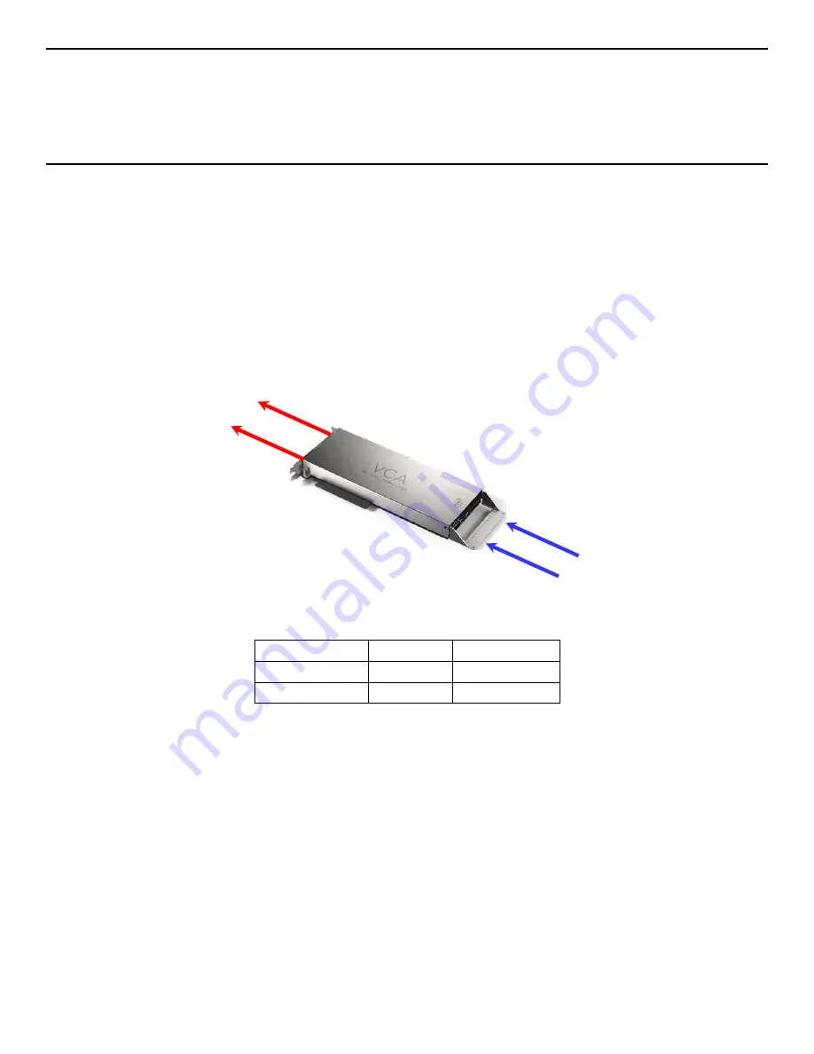
The following illustration and table identify the thermal, air flow, and air pressure requirements that must be
met by a chassis following a common front of system to back of system air flow pattern.
Card Inlet Temp
*Flow Rate
*Pressure Drop
45° C
25.5 CFM
0.476 “H
2
O
35° C
18.0 CFM
0.246 “H
2
O
*CFM=Cubic Feet per Minute
*“H
2
O= Inches of Water
Some custom chassis configurations may orient the card such that the air flow is reversed from the standard
air flow pattern shown above. In these non-standard system configurations the thermal, air flow, and air
pressure boundary conditions must meet the following requirements.
Air Flow In
(Card Inlet)
Air Flow Out
Standard Air Flow Pattern
Содержание VCA1283LVV
Страница 2: ......


