
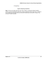


Hot-Swap SCSI Backplane
SR2300 2U Server Chassis Technical Product Specification
Intel Order Number A94546-004
40
SR2300
Hot-swap SCSI Backplane using two Unitrode* UCC5638 Multi-mode SCSI 15 line
terminators.
6.2.7 Power
Control
Power control on the SR2300 hot-swap SCSI backplane supports the following features:
•
Power-down of a drive when a failure is detected and reported (using enclosure services
messages) via the SCSI bus. This decreases the likelihood that the drive is damaged
during removal from the hot-swap drive bay. When a new drive is inserted, the power
control waits a short amount of time for the drive to be fully seated before applying
power to the drive.
•
If the system power is on, the Hot-swap SCSI Backplane immediately powers off a drive
slot when it detects that a drive has been removed. This prevents possible damage to
the drive when it is partially removed and re-inserted while full power is available, and
prevents disruption of the entire SCSI array from possible sags in supply voltage and
resultant current spikes.
•
Hot-spare drive support: Spare drives remain in the hot-swap bay, but are left un-
powered until a drive is determined to have failed. In case of a drive failure, the hot
spare can be powered up and put into service automatically without requiring immediate
operator intervention to replace the drive.
•
The hot-swap SCSI backplane will automatically bypass the power control circuitry if a
shorted drive is inserted or if a drive develops a short during operation. This prevents the
hot-swap SCSI backplane from being damaged by a drive that draws excessive current.
6.3 Power
Connector
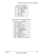
The SCSI backplane provides power to the seven drive bays, supporting up to seven hard disk
drives, or six hard disk drives and the optional Floppy/CDROM Module. A 6-pin power cable is
routed from the Power Distribution Board and plugs into 2x3 shrouded plastic PC power
connector on the SCSI backplane. The following table shows the power connector pin-out.
Table 17. SCSI Backplane Power Connector Pin-out
Pin
Name
Pin
Name
1 GND 4 +12V
2 GND 5 +12V
3 +5V 6 +3.3V
Содержание SR2300 - FRONT BEZEL BLK
Страница 10: ......


