


Power Sub-system
SR2300 2U Server Chassis Technical Product Specification
Intel Order Number A94546-004
18
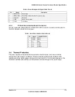
2.3.1
P1 Baseboard Connector
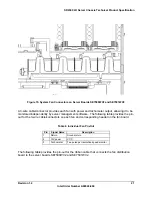
A 24-pin Molex* 39-01-2245 connector and harness from the power supply provides the server
boards SE7500WV2 and SE7501WV2 with the required voltages and interface signals. The
following table provides the connector pin-out.
Table 5. 24-pin Baseboard Power Connector Pin-out
Pin
Signal
18 AWG COLOR
Pin
Signal
18 AWG COLOR
1 +3.3
Vdc
Orange
13 +3.3Vdc Orange
2 +3.3
Vdc
Orange
14 -12Vdc Blue
3 COM Black
15 COM Black
4 +5
Vdc Red
16 PS_ON# Green
5 COM
Orange
17 COM Black
6 +5
Vdc Red
18 COM Black
7 COM Black
19 COM Black
8 PWR
OK
Gray
20 Reserved
NC
9 5
VSB Purple
21 +5VDC Red
10 +12
Vdc Yellow
22 +5VDC Red
11 +12
Vdc Yellow
23 +5VDC Red
12 +3.3
Vdc Orange
24 COM
Black
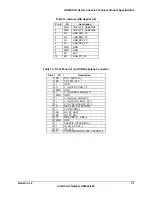
2.3.2
P2 Power Management Signal Cable
An 8-pin Molex 39-01-2080 connector and harness from the power supply connects to the
server boards SE7500WV2 and SE7501WV2 to provide power to the processor subsystem.
The following table provides the connector pin-out.
Pin Signal
1 Common
2 Common
3 Common
4 Common
5 +12V3
6 +12V3
7 +12V3
8 +12V3
2.3.3
P3 Power Management Signal Cable
A 5-wire cable with a Molex 50-57-9405 female housing connector is used to direct power
management signals to the server boards SE7500WV2 and SE7501WV2. The following table
shows the pin-out.
Содержание SR2300 - FRONT BEZEL BLK
Страница 10: ......


