


List of Figures
Local Control Panel Kit Install Guide
vii
List of Figures
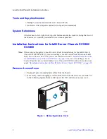
Figure 1. Removing Access Cover............................................................................................. 2
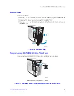
Figure 2. Removing Bezel Assembly ......................................................................................... 3
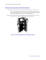
Figure 3. Removing Outer Bezel Door from Bezel Assembly ................................................... 4
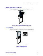
Figure 4. Removing Upper One-third of Bezel Grill ................................................................... 5
Figure 5. Installing LCP Grill....................................................................................................... 5
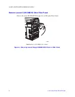
Figure 6. Removing Lowest Floppy/CD-ROM/DVD Drives or Filler Panel ................................. 6
Figure 7. Installing EMI Shield on LCP Carrier........................................................................... 7
Figure 8. Attaching Drive Rails to LCP Carrier........................................................................... 7
Figure 9. Installing LCP Carrier .................................................................................................. 8
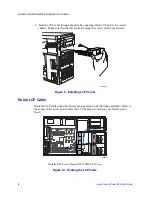
Figure 10. Routing the LCP Cable ............................................................................................ 8
Figure 11. Attaching LCP Cable to Header on Intel® Server Board SE7520AF2 ..................... 9
Figure 12. Attaching LCP Cable to Header on Intel® Server Board SE7520BD2 .................. 10
Figure 13. Installing Inner Bezel Door ...................................................................................... 11
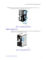
Figure 14. Replacing Access Cover ......................................................................................... 11
Figure 15. Removing Access Cover......................................................................................... 12
Figure 16. Removing Bezel ...................................................................................................... 13
Figure 17. Removing Lowest Floppy/CD-ROM/DVD Drives or Filler Panel ............................. 13
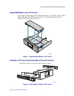
Figure 18. Installing EMI Shield on LCP Carrier....................................................................... 14
Figure 19. Installing Drive Rails to LCP Carrier........................................................................ 14
Figure 20. Inserting LCP Carrier into Drive Bay ....................................................................... 15
Figure 21. Routing LCP Cable in Intel® Entry Server Chassis SC5275-E............................... 15
Figure 22. Attaching LCP Cable to Header on Intel® Server Board SE7520AF2 ................... 16
Figure 23. Attaching LCP Cable to Header on Intel® Server Board SE7520BD2 ................... 17
Figure 24. Installing Bezel ........................................................................................................ 18
Figure 25. Replacing Access Cover ......................................................................................... 18
Figure 26. Removing Access Cover......................................................................................... 19
Figure 27. Removing Bezel ...................................................................................................... 20
Figure 28. Removing Lowest Floppy/CD-ROM/DVD Drives or Filler Panel ............................. 20
Figure 29. Installing EMI Shield on LCP Carrier....................................................................... 21
Figure 30. Inserting LCP Carrier into Drive Bay ....................................................................... 22
Figure 31. Routing LCP Cable ................................................................................................. 22
Figure 32. Attaching LCP Cable to Header on Intel® Server Board S5000VSA ..................... 23
Figure 33. Attaching LCP Cable to Header on Intel® Server Board S5000PSL or Intel® Server
Board XVN ......................................................................................................................... 23
Figure 34. Installing Bezel ........................................................................................................ 24
Figure 35. Replacing Access Cover ......................................................................................... 25


