Intel SC5275-E BRP Скачать руководство пользователя страница 23

Local Control Panel Kit Installation Instructions

Local Control Panel Kit Install Guide

15

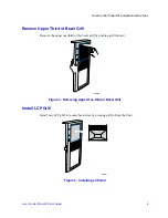
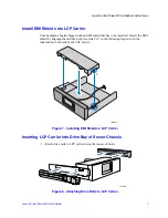
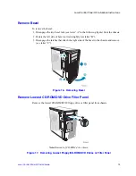
2. Feed the cable in first. Slide the LCP carrier into desired 5.25-in drive bay and secure 

with two screws to the front of chassis.

Figure 20.  Inserting LCP Carrier into Drive Bay
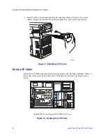
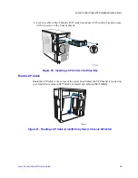
Route LCP Cable

Route the LCP cable to the corner of the server board where the LCP header is located on 
your Intel® Server Board SE7520AF2 or Intel® Server Board SE7520BD2.

Figure 21.  Routing LCP Cable in Intel® Entry Server Chassis SC5275-E

TP00646

Содержание SC5275-E BRP

Страница 1: ...ver Chassis SC5275 E UP DP WS BRP Intel Entry Server Chassis SC5299 E DP WS BRP Intel Server Chassis SC5300 Intel Server Chassis SC5400 A Guide for Technically Qualified Assemblers of Intel Identified...

Страница 2: ...ake changes to specifications and product descriptions at any time without notice Intel server boards contain a number of high density VLSI and power delivery components that need adequate airflow for...

Страница 3: ...ntel com support motherboards server sb cs 010770 htm Consignes de s curit Lisez attention toutes les consignes de s curit et les mises en garde indiqu es dans ce document avant de suivre toute instru...

Страница 4: ...ment damage can result Electrostatic discharge ESD and ESD protection ESD can damage disk drives boards and other parts We recommend that you perform all procedures in this chapter only at an ESD work...

Страница 5: ...ier 7 Inserting LCP Carrier into Drive Bay of Server Chassis 7 Route LCP Cable 8 Connect LCP Cable to LCP Header of Server Board 9 Replace Bezel Assembly 10 Replace Access Cover 11 Installation Instru...

Страница 6: ...Contents vi Local Control Panel Kit Install Guide Replace Bezel 24 Replace Access Cover 25...

Страница 7: ...re 17 Removing Lowest Floppy CD ROM DVD Drives or Filler Panel 13 Figure 18 Installing EMI Shield on LCP Carrier 14 Figure 19 Installing Drive Rails to LCP Carrier 14 Figure 20 Inserting LCP Carrier i...

Страница 8: ...List of Figures viii Local Control Panel Kit Install Guide...

Страница 9: ...Before converting your system to a rack mount configuration observe these safety guidelines 1 Turn off all peripheral devices connected to the server 2 Turn off the server by pressing the power button...

Страница 10: ...tions for the Intel Server Chassis SC5300 SC5400 If you are installing a Local Control Panel kit into an Intel Entry Server Chassis SC5275 E follow the instructions under Installation Instructions for...

Страница 11: ...e than 40 degrees outward At a 40 degree angle push the bezel assembly away from the chassis see letter C If the bezel assembly does not immediately disconnect from the chassis then tap the left hand...

Страница 12: ...he inner bezel door use your other hand to push the outer bezel door away from the inner bezel door The outer bezel door will disengage from the inner bezel door at the four hinges see letter A in the...

Страница 13: ...ve Upper Third of Bezel Grill Remove the upper one third of the bezel grill by pushing grill forward Figure 4 Removing Upper One third of Bezel Grill Install LCP Grill Install new LCP grill into outer...

Страница 14: ...Control Panel Kit Install Guide Remove Lowest CD ROM DVD Drive Filler Panel Remove the lowest CD ROM DVD Floppy drive or filler panel from chassis Note Removal of CD ROM drive shown Figure 6 Removing...

Страница 15: ...o be installed Install the EMI shield by aligning the middle tooth see letter A in the following figure with the indentation in the side of the LCP carrier Figure 7 Installing EMI Shield on LCP Carrie...

Страница 16: ...sure that the drive rails are using the correct slots in the chassis Figure 9 Installing LCP Carrier Route LCP Cable Route the LCP cable under the chassis fan area along side the floppy and IDE cables...

Страница 17: ...tall Guide 9 Connect LCP Cable to LCP Header of Server Board 1 Connect the LCP cable to the LCP header on the server board 2 For an Intel Server Board SE7520AF2 use header J1J1 on the server board Fig...

Страница 18: ...ezel Assembly Fit the right hand side of the inner bezel door against the right hand side of chassis and engage plastic bezel hooks see letter A in the following figure into raised metal slots at chas...

Страница 19: ...than a 40 degree angle or you may damage the bezel hooks at the right hand side of the door Figure 13 Installing Inner Bezel Door Replace Access Cover Replace access cover and slide forward to secure...

Страница 20: ...g a Local Control Panel kit into an Intel Entry Server Chassis SC5299 E follow the instructions under Installation Instructions for Intel Entry Server Chassis SC5299 E on page 19 Remove Access Cover W...

Страница 21: ...2 Rotate the left side of bezel outward slightly see letter B 3 Disengage the latches that attach the right side of the bezel to the chassis and remove see letter C Figure 16 Removing Bezel Remove Lo...

Страница 22: ...g the middle tooth see letter A in the following figure with the indentation in the side of the LCP carrier Figure 18 Installing EMI Shield on LCP Carrier Inserting LCP Carrier into Drive Bay of Serve...

Страница 23: ...in drive bay and secure with two screws to the front of chassis Figure 20 Inserting LCP Carrier into Drive Bay Route LCP Cable Route the LCP cable to the corner of the server board where the LCP heade...

Страница 24: ...Install Guide Connect LCP Cable to LCP Header on Server Board 1 Connect the LCP cable to the LCP header on the server board 2 For an Intel Server Board SE7520AF2 use header J1J1 on the server board Fi...

Страница 25: ...Cable to Header on Intel Server Board SE7520BD2 Replace Bezel 1 If necessary remove filler panel from bezel that corresponds to the position of the LCP carrier 2 Engage the three clips see letter A in...

Страница 26: ...Installing Bezel Replace Access Cover To replace the access cover 1 Position access cover on chassis see letter A in the following figure 2 Slide the two thumb latches see letter B to the CLOSED posit...

Страница 27: ...ard SC5275 E follow the instructions in Installation Instructions for Intel Entry Server Chassis SC5275 E on page 12 Remove Access Cover When your chassis is upright in a tower pedestal position and y...

Страница 28: ...e the latches that attach the right side of the bezel to the chassis and remove see letter C Figure 27 Removing Bezel Remove Lowest CD ROM DVD Drive Filler Panel Remove the lowest CD ROM DVD floppy dr...

Страница 29: ...EMI Shield onto LCP Carrier Your backplane board shipped with an EMI shield that has to be installed Install the EMI shield by aligning the middle tooth see letter A in the following figure with the i...

Страница 30: ...CP carrier into the desired 5 25 in drive bay Feed the cable in first Figure 30 Inserting LCP Carrier into Drive Bay Route LCP Cable Route the LCP cable to the corner of the server board where the LCP...

Страница 31: ...on the server board 2 For an Intel Server Board S5000VSA use header J1J6 on the server board Figure 32 Attaching LCP Cable to Header on Intel Server Board S5000VSA 3 For an Intel Server Board S5000PSL...

Страница 32: ...hree clips see letter A in the following figure at the right edge of the bezel with the corresponding latches on the right side of the chassis 3 Engage the clips with the slots see letter B 4 Rotate t...

Страница 33: ...o replace the access cover 1 Slide the access cover on the chassis and latch securely see letter A in the following figure 2 optional Replace shipping screws see letter B Caution This chassis must be...

Страница 34: ...Local Control Panel Kit Installation Instructions 26 Local Control Panel Kit Install Guide...

Отзывы: