9
General Installation Process
18
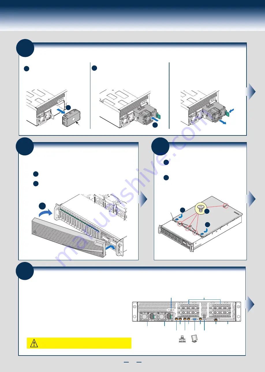
Install Second Power Supply Module (optional)
A
B
Finger Hole
A
Use the 'finger hole' to remove the
filler panel.
B
Insert the power supply module into the power
supply cage and push all the way until it clicks
into place.
Power Supply Removal:
Pull out the module from the chassis by holding
the handle and pressing the green latch in the
direction shown.
21
Finishing Up
1
st
Power
Supply
Module
2
nd
Power
Supply
Module
Serial
Port A
Intel
®
RMM4
NIC Port
Intel
®
I/O
Module
(optional)
Serial Port B (optional)
Add-in Card Slots
Network
Video
USB
Ports
NIC 1 NIC 3
NIC 2 NIC 4
1. Verify the system top cover is installed.
2. Install the server into the rack using the instructions provided with the rack
mounting kit.
3. Connect your USB keyboard/mouse, video and other I/O cables/devices
as shown.
Then connect the power cord(s).
CAUTION:
This system must be operated with the TOP COVER installed to
ensure proper cooling.
Before installing your operating system, you must finish your system
installation, make I/O connections, and plug in power cord(s).
20
Install the Top Cover
A
Install the three screws at the front and torque to
7-9in-lbs. Then install the screw at the back and
torque to 7-9in-lbs.
B
Place the top cover on system and slide towards the
front of the chassis until the recessed front edge is fully
engaged.
B
A
A
Recessed
Edge
A
19
Install Bezel (optional)
A
B
Lock the right end of the front bezel to the rack handle.
Push in the left side of the bezel until it clicks into place.
Lock the bezel if needed.
NOTE: Before installing the bezel, you must install the rack handles.
B
Содержание R2000GL series
Страница 2: ...This page is intentionally left blank...
Страница 22: ...G31061 004...


