background image

Installing and Replacing Server Board Components


Intel

®

 Server Board S1200KP Product Guide 

21 

Installing and Removing the Server Board 


CAUTION 

Only qualified technical personnel should perform this procedure. 
Disconnect the computer from its power source before performing the 
procedures described here. Failure to disconnect the power before you open 
the computer can result in personal injury or equipment damage.  


Refer to your 

Chassis Manual

 for instructions on installing and removing the Server Board.  

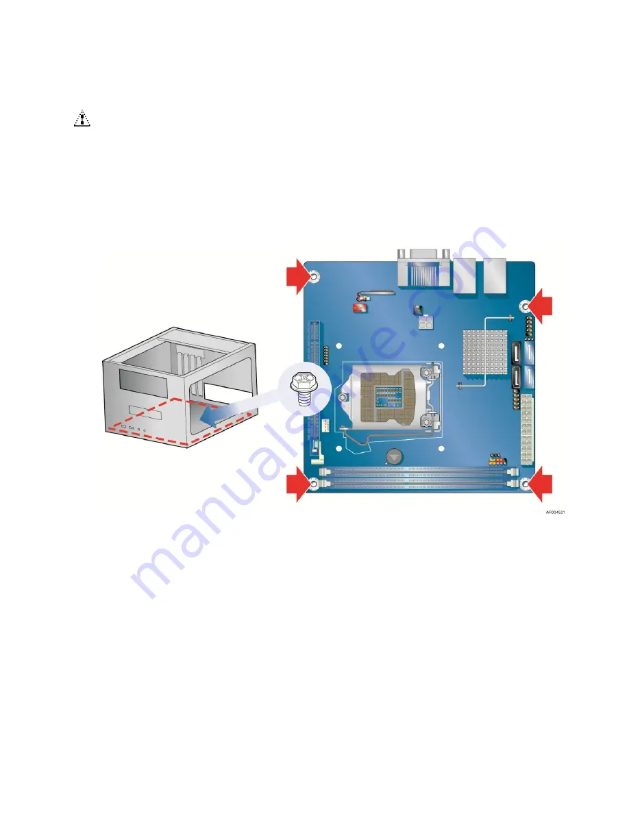
Figure 5 shows the location of the mounting screw holes for Intel

®

 Server Board S1200KP.  


Figure 5. Intel

®

 Server Board S1200KP Mounting Screw Hole Locations 

Содержание DBS1200KP

Страница 1: ...Intel Server Board S1200KP Product Guide Order Number G39481 003 ...

Страница 2: ...fe sustaining applications Intel may make changes to specifications and product descriptions at any time without notice Intel Server Board S1200KP may contain design defects or errors known as errata which may cause the product to deviate from published specifications Current characterized errata are available on request Contact your local Intel sales office or your distributor to obtain the lates...

Страница 3: ...arm systems test equipment etc may not be supported without further evaluation by Intel Document Organization The chapters in this Product Guide are arranged as follows 1 Server Board Features a summary of product features 2 Installing and Replacing Server Board Components instructions on how to install the Server Board and other hardware components 3 Updating the BIOS instructions on how to updat...

Страница 4: ...Preface iv Intel Server Board S1200KP Product Guide Term Description MB Megabyte 1 048 576 bytes Mb Megabit 1 048 576 bits MHz Megahertz one million hertz ...

Страница 5: ...8 VGA Displays 8 PCI Express x16 Graphics 8 LAN Subsystem 10 USB Support 10 SATA Support 10 Expandability 11 Legacy I O 11 BIOS 11 SATA Auto Configuration 11 PCI PCI Express Auto Configuration 11 Security Passwords 11 Hardware Management 12 Hardware Monitoring and Fan Speed Control 13 Fan Monitoring 13 Chassis Intrusion 13 Power Management 13 Software Support 13 ACPI 13 Hardware Support 14 Power C...

Страница 6: ...CI Express x16 Graphics Card 30 Removing a PCI Express x16 Graphics Card 32 Connecting SATA Drives 33 Connecting to the Internal Headers 34 Chassis Intrusion Header 34 Front Panel USB 2 0 Headers 35 Front Panel Header 35 Alternate Front Panel Power LED Header 35 Low Pin Count LPC Debug header 36 Connecting Chassis Fan and Power Supply Cables 37 Connecting a Chassis Fan 37 Connecting Power Supply C...

Страница 7: ...Install the Processor 24 Figure 10 Secure the Load Plate in Place 25 Figure 11 Connecting the Processor Fan Heat Sink Power Cable to the Processor Fan Header 26 Figure 12 Dual Channel Memory Configuration Example 27 Figure 13 Use DDR3 DIMMs 28 Figure 14 Installing a DIMM 29 Figure 15 Installing a PCI Express x16 Graphics Card 31 Figure 16 Removing a PCI Express x16 Graphics Card 32 Figure 17 Conne...

Страница 8: ...ssis Intrusion Header Signal Names 34 Table 5 USB 2 0 Header Signal Names 35 Table 6 Front Panel Header Signal Names 35 Table 7 Alternate Front Panel Power LED Header Signal Names 35 Table 8 LPC Debug Header 36 Table 9 Jumper Settings for the BIOS Setup Program Modes 40 Table 10 BIOS Beep Codes 46 Table 11 Front panel Power LED Blink Codes 46 Table 12 BIOS Error Messages 47 ...

Страница 9: ...Tables Intel Server Board S1200KP Product Guide ix This page is intentionally left blank ...

Страница 10: ... Core i3 Processors DIMMs Support for 1Gb 2Gb and 4Gb memory technology Support for up to 16 GB of system memory with two DIMMs using 4 Gb memory technology Support for ECC and non ECC memory 3 Chipset Intel C206 Platform Controller Hub PCH Chipset Graphics Integrated graphics support for processors with Intel Graphics Technology DVI I Discrete graphics support for PCI Express 2 0 x16 with Intel X...

Страница 11: ...e to detect out of range power supply voltages Thermal sense to detect out of range thermal values Two fan headers Two fan sense inputs used to monitor fan activity Fan speed control Notes 1 Pairing a mini ITX chassis and more than 65W TDP processor with the supplied standard Intel thermal solution may not meet Intel s thermal requirement standard Please verify that your thermal solution and chass...

Страница 12: ...edition Microsoft Windows 7 Ultimate 32 bit edition Microsoft Windows 7 Home Basic 64 bit edition Microsoft Windows 7 Home Premium 64 bit edition Microsoft Windows 7 Home Premium 32 bit edition Microsoft Windows 7 Home Basic 32 bit edition Microsoft Windows Server 2008 R2 SP1 with Hyper v Microsoft Windows Small Business Server 2011 Essentials Redhat Enterprise Linux 6 0 SUSE Linux Enterprise Serv...

Страница 13: ...eatures 4 Intel Server Board S1200KP Product Guide Server Board Components Figure 1 shows the approximate location of the major components on Intel Server Board S1200KP Figure 1 Intel Server Board S1200KP Components ...

Страница 14: ...n jumper block E SATA connectors F Intel C206 Chipset G Front panel USB 2 0 header H Main power connector 2 x 12 I Front panel header J DIMM 1 Channel A DIMM 1 K DIMM 2 Channel B DIMM 1 L Alternate front panel power LED header M Piezoelectric speaker N Standby power LED O Processor fan header P LGA1155 processor socket Q PCI Express x16 bus add in card connector R Low Pin Count LPC Debug header S ...

Страница 15: ...el Xeon E3 1200 Processors the 2nd Generation Intel Core i3 Processors Intel Xeon E3 1200 V2 Processors or the 3rd Generation Intel Core i3 Processors with up to 95W TDP in an LGA1155 socket Processors are not included with the Server Board and must be purchased separately The processor connects to the Server Board through the LGA1155 socket NOTE The product codes of DBS1200KP and BBS1200KP can on...

Страница 16: ... screen at power up The BIOS will attempt to configure the memory controller for normal operation 2 ECC DIMMs are recommended to use for server system The board has two DDR3 DIMM sockets arranged in two channels and supports the following memory features Two independent memory channels with interleaved mode support Support for ECC and non ECC DIMMs Unbuffered single sided or double sided DIMMs wit...

Страница 17: ...eo formats Blu ray Stereoscopic 3D via HDMI 1 4 Intel HD Technology with advanced hardware video transcoding Dynamic Video Memory Technology DVMT 5 0 support including support of up to 1 7 GB Video Memory with a 4 GB and above system memory configuration Digital Visual Interface DVI I The DVI I port supports both digital and analog DVI displays The maximum supported resolution is 1900 x 1200 WUXGA...

Страница 18: ...usly for an aggregate of 32 GB s when operating in x16 GEN3 mode Supports PCI Express GEN2 frequency of 5 GHz resulting in 5 0 Gb s each direction 500 MB s per lane The maximum theoretical bandwidth on the interface is 8 GB s in each direction simultaneously for an aggregate of 16 GB s when operating in x16 GEN2 mode Supports PCI Express GEN1 frequency of 2 5 GHz resulting in 2 5 Gb s each directi...

Страница 19: ...D LED Color LED State Indicates A Link Activity C Link Activity Green Off LAN link is not established On LAN link is established Blinking LAN activity is occurring B Link Speed D Link Activity N A Off 10 Mb s data rate Green On 100 Mb s data rate Yellow On 1000 Mb s data rate USB Support The Server Board supports eight USB 2 0 ports four ports routed to back panel connectors and four ports routed ...

Страница 20: ...all a SATA device such as a hard drive in your computer the auto configuration utility in the BIOS automatically detects and configures the device for your computer You do not need to run the BIOS Setup program after installing a SATA device You can override the auto configuration options by specifying manual configuration in the BIOS Setup program PCI PCI Express Auto Configuration If you install...

Страница 21: ...layed before the computer is booted If only the supervisor password is set the computer boots without asking for a password If both passwords are set you can enter either password to boot the computer For instructions on resetting the password go to Clearing Passwords on page 40 Hardware Management The hardware management features of Intel Server Board S1200KP enable the board to be compatible wit...

Страница 22: ... third party software Chassis Intrusion The board supports a chassis security feature that detects if the chassis cover has been removed The security feature uses a mechanical switch on the chassis that can be connected to the chassis intrusion header on the Server Board See Figure 1 for the location of the chassis intrusion header Power Management Power management is implemented at several levels...

Страница 23: ...in the ACPI S3 S4 or S5 state Each fan header is wired to a tachometer input All fan headers support closed loop fan control that can adjust the fan speed or switch the fan on or off as needed All fan headers have a 12 V DC connection up to 12 V DC when using 3 wire chassis fans All fan headers are controlled by Pulse Width Modulation The chassis fan header supports linear fan control on 3 wire fa...

Страница 24: ...last known wake state When signaled by a wake up device or event the computer quickly returns to its last known awake state The Server Board supports the PCI Bus Power Management Interface Specification Add in cards that support this specification can participate in power management and can be used to wake the computer The use of Instantly Available PC technology requires operating system support ...

Страница 25: ...er Board S1200KP Product Guide Figure 3 Location of the Standby Power Indicator For more information on standby current requirements for the Server Board refer to the Technical Product Specification at http www intel com products server ...

Страница 26: ...ption of the board s beep codes Real Time Clock Subsystem A coin cell battery CR2032 powers the real time clock and CMOS memory When the computer is not plugged into a wall socket the battery has an estimated life of three years When the computer is plugged in the standby current from the power supply extends the life of the battery The clock is accurate to 13 minutes year at 25 ºC with standby po...

Страница 27: ...urce and from any telecommunications links networks or modems before performing any of the procedures described in this chapter Failure to disconnect power telecommunications links networks or modems before you open the computer or perform any procedures can result in personal injury or equipment damage Some circuitry on the board can continue to operate even though the front panel power button is...

Страница 28: ...put To avoid overloading the power supply make sure that the calculated total current loads of all the modules within the computer is less than the output current rating of each of the power supplies output circuits plus enough headroom for server board power consumption Observe Safety and Regulatory Requirements Read and follow the instructions in this section and the instructions supplied with t...

Страница 29: ...smissions protects internal components from dust and foreign objects and promotes correct airflow within the chassis Install the I O shield before installing the Server Board in the chassis Place the shield inside the chassis as shown in Figure 4 Press the shield into place so that it fits tightly and securely If the shield does not fit obtain a properly sized shield from the chassis supplier Figu...

Страница 30: ...uter from its power source before performing the procedures described here Failure to disconnect the power before you open the computer can result in personal injury or equipment damage Refer to your Chassis Manual for instructions on installing and removing the Server Board Figure 5 shows the location of the mounting screw holes for Intel Server Board S1200KP Figure 5 Intel Server Board S1200KP M...

Страница 31: ...removing a processor make sure the AC power has been removed by unplugging the power cord from the computer the standby power LED should not be lit see Figure 3 on page 16 Failure to do so could damage the processor and the board To install a processor follow these instructions 1 Observe the precautions in Before You Begin in page 18 2 Unlatch the processor socket lever by pushing it down and away...

Страница 32: ...duct Guide 23 3 Rotate the socket lever to lift the load plate away from the socket Figure 7 A Make sure that the load plate is in the fully open position Figure 7 B while being careful not to damage adjacent components Do not touch the socket contacts Figure 7 Lift the Load Plate ...

Страница 33: ... processor with your thumb and index finger oriented as shown in Figure 9 to align your fingers with the socket finger cutouts Make sure that the processor Pin 1 indicator gold triangle is aligned with the Pin 1 chamfer on the socket Figure 9 B and that the notches on the processor align with the posts on the socket Figure 9 C Lower the processor straight down without tilting or sliding it in the ...

Страница 34: ...ab Figure 10 C D The socket cover Figure 10 B will pop off as shown Figure 10 Secure the Load Plate in Place 7 Pick up the socket cover and remove it from the server board NOTE Do not discard the socket cover save it for possible future use Always replace the socket cover if you remove the processor from the socket ...

Страница 35: ... the boxed processor manual or boxed thermal solution manual Connecting the Processor Fan Heat Sink Cable Connect the processor fan heat sink power cable to the 4 pin processor fan header see Figure 11 A fan with a 4 pin connector as shown in Figure 11 is recommended Figure 11 Connecting the Processor Fan Heat Sink Power Cable to the Processor Fan Header Removing the Processor For instructions on ...

Страница 36: ...ta structure The server board has two 240 pin DDR3 DIMM sockets providing Channel A and Channel B For dual channel performance install a matched pair of DIMMs equal in speed and size see Figure 12 Figure 12 Dual Channel Memory Configuration Example NOTE The Intel Xeon E3 1200 Processors the 2nd Generation Intel Core i3 Processors Intel Xeon E3 1200 V2 Processors or the 3rd Generation Intel Core i3...

Страница 37: ...omponents 28 Intel Server Board S1200KP Product Guide Installing DIMMs To make sure you have the correct DIMM place it on the illustration of the DDR3 DIMM in Figure 13 All the notches should match with the DDR3 DIMM Figure 13 Use DDR3 DIMMs ...

Страница 38: ...ckets see Figure 14 4 If a full length PCI Express graphics card is installed in the PCI Express x16 connector remove the card to gain full access to the DIMM sockets Figure 14 Installing a DIMM 5 Make sure the clips at either end of the DIMM socket s are pushed outward to the open position 6 Holding the DIMM by the edges remove it from its anti static package 7 Position the DIMM above the socket ...

Страница 39: ...he DIMM socket The DIMM pops out of the socket 7 Hold the DIMM by the edges lift it away from the socket and store it in an anti static package 8 Reinstall the PCI Express graphics card if one was removed in Step 5 and reconnect any other parts you removed or disconnected to reach the DIMMs 9 Replace the computer s cover and reconnect the AC power cord Installing and Removing PCI Express x16 Graph...

Страница 40: ...PCI Express x16 connector Figure 15 A and press down on the card until it is completely seated in the connector and the card retention notch on the card snaps into place around the retention mechanism pin on the connector 3 Secure the card s metal bracket to the chassis back panel with a screw Figure 15 B 4 Connect a monitor to the graphics card according to the manufacturer s instructions Figure ...

Страница 41: ...s in Before You Begin on page 18 2 Disconnect the monitor cable from the graphics card back panel connector 3 Remove the screw Figure 16 A that secures the card s metal bracket to the chassis back panel 4 Push the card ejector lever down using the tip of a pencil or similar tool Figure 16 B in the notch This will release the card from the connector C 5 Pull the card straight up to remove it Figure...

Страница 42: ... SATA connectors The blue SATA connectors support 6 0 Gb s and slower speed SATA devices while the black SATA connectors support 3 0 Gb s and slower speed SATA devices For correct cable function 1 Observe the precautions in Before You Begin on page 18 2 Attach one end of the SATA cable to one of the SATA connectors on the board Figure 17 A and attach the other end of the cable to the SATA drive da...

Страница 43: ...er Board S1200KP Figure 18 Internal Headers Chassis Intrusion Header Figure 18 A shows the location of the chassis intrusion header This header can be connected to a mechanical switch on the chassis to detect if the chassis cover is removed This switch should be in the open position when the chassis cover is installed and closed when the cover is removed Table 4 shows the pin assignments and signa...

Страница 44: ...t 2 Front panel LED Out 3 Hard disk active LED Out 4 Front panel LED Out Reset Switch On Off Switch 5 Ground 6 Power switch In 7 Reset switch In 8 Ground Power Not Connected 9 Power Out 10 No pin NOTE When connecting individual wires from your chassis front panel to the front panel header be sure to observe the connection polarity Positive wires are usually solid color and negative wires are usual...

Страница 45: ...ure 18 E shows the location of the low pin count debug header Table 8 shows the pin assignments and signal names for the low pin count debug header Table 8 LPC Debug Header Pin Signal Name Pin Signal Name 1 CK_33M_DEBUG 2 GND 3 PLTRST 4 LFRAME 5 LAD0 6 LAD1 7 LAD2 8 LAD3 9 GND 10 GND 11 3 3 V 12 3 3 V 13 Not Connected 14 3 3 V ...

Страница 46: ...1200KP Product Guide 37 Connecting Chassis Fan and Power Supply Cables Connecting a Chassis Fan Connect the chassis fan cable to the chassis fan header on the Server Board Figure 19 shows the location of the chassis fan header Figure 19 Location of the Chassis Fan Header ...

Страница 47: ...he 2 x 12 pin main power connector Figure 20 B is backwards compatible with ATX12V power supplies with 2 x 10 connectors NOTE If your power supply has a 2 x 10 main power connector it is recommended that you do not install a PCI Express x16 graphics card unless it has a direct connection to the power supply Figure 20 Connecting Power Supply Cables 1 Observe the precautions in Before You Begin on p...

Страница 48: ...umper NOTE Always turn off the power and unplug the power cord from the computer before moving the jumper Moving the jumper with the power on may result in unreliable computer operation Figure 21 shows the location of the Server Board s BIOS configuration jumper block Figure 21 Location of the BIOS Configuration Jumper Block ...

Страница 49: ... 1 Observe the precautions in Before You Begin on page 18 2 Turn off all peripheral devices connected to the computer Turn off the computer Disconnect the computer s power cord from the AC power source wall outlet or power adapter 3 Remove the computer cover 4 Find the configuration jumper block see Figure 21 5 Place the jumper on pins 2 3 as shown below 6 Replace the cover plug in the computer tu...

Страница 50: ... 22 on page 42 shows the location of the battery CAUTION You will have the risk of explosion if the battery is replaced incorrectly Batteries should be recycled if possible Disposal of used batteries must be in accordance with local environmental regulations To replace the battery follow these steps 1 Observe the precautions in Before You Begin see page 18 2 Turn off all peripheral devices connect...

Страница 51: ...Installing and Replacing Server Board Components 42 Intel Server Board S1200KP Product Guide Figure 22 Removing the Battery ...

Страница 52: ...ate the BIOS The BIOS update file contains New BIOS file including the Intel Management Engine Intel ME Firmware Image Intel Integrator Toolkit Configuration File optional Intel Flash Memory Update Utility You can obtain either of these files through your computer supplier or by navigating to the Intel Server Board S1200KP page on the Intel World Wide Web site Download Center at http downloadcente...

Страница 53: ...function properly 1 Uncompress the BIOS update file and copy the BIO file IFLASH EXE and ITK file optional to a bootable USB flash drive or other bootable USB media 2 Configure the BIOS or use the F10 option during POST to boot to the USB device 3 Manually run the IFLASH EXE file from the USB device and manually update the BIOS ...

Страница 54: ...the BIOS Flash Update tool 7 Select the USB thumb drive and press Enter 8 Select the BIO file and press Enter 9 Confirm you want to update the BIOS by pressing Enter 10 Wait 2 5 minutes for the update to complete 11 Remove the thumb drive 12 Restart the computer Recovering the BIOS It is unlikely that anything will interrupt the BIOS update however if an interruption occurs the BIOS could be damag...

Страница 55: ...phics card Memory error On off 1 0 second each three times then a 2 5 second pause off the entire pattern repeats beeps and pause until the system is powered off 932 Hz Thermal trip warning Alternate high and low beeps 1 0 second each for eight beeps followed by system shut down High beep 2000 Hz Low beep 1500 Hz Table 11 Front panel Power LED Blink Codes Type Pattern Note F2 Setup F10 Boot Menu P...

Страница 56: ...f the BIOS error messages Table 12 BIOS Error Messages Error Message Explanation CMOS Battery Low The battery may be losing power Replace the battery soon CMOS Checksum Bad The CMOS checksum is incorrect CMOS memory may have been corrupted Run Setup to reset values Memory Size Decreased Memory size has decreased since the last boot If no memory was removed then memory may be bad No Boot Device Ava...

Отзывы: