Product Description
23
1.5
Intel
®
B85 Express Chipset
Intel B85 Express Chipset with Direct Media Interface (DMI) interconnect provides
interfaces to the processor and USB, SATA, LPC, LAN, and PCI Express. The Intel B85
Express Chipset is a centralized controller for the board’s I/O paths.
For information about
Refer to
The Intel B85 chipset
http://www.intel.com/products/desktop/chipsets/index.htm
Resources used by the chipset
Chapter 2
1.5.1
Direct Media Interface (DMI)
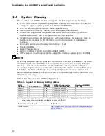
Direct Media Interface (DMI) is the chip-to-chip connection between the processor and
the PCH. This high-speed interface integrates advanced priority-based servicing
allowing for concurrent traffic and true isochronous transfer capabilities.
1.5.2
USB
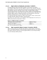
The PCH contains up to two Enhanced Host Controller Interface (EHCI) host controllers
that support USB high-speed signaling. High-speed USB 2.0 allows data transfers up to
480 Mb/s. All ports are high-speed, full-speed, and low-speed capable.
The PCH also contains an integrated eXtensible Host Controller Interface (xHCI) host
controller which supports USB 3.0 ports. This controller allows data transfers up to
5 Gb/s. The controller supports SuperSpeed (SS), high-speed (HS), full-speed (FS),
and low-speed (LS) traffic on the bus.
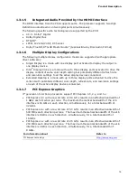
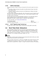
The Intel B85 Express Chipset provides the USB controller for the USB 2.0/3.0 ports.
The port arrangement is as follows:
•
USB 3.0 ports:
Two USB 3.0 ports are implemented with stacked back panel connectors
Two front panel USB 3.0 ports are implemented through one internal connector
•
USB 2.0 ports:
Four ports are implemented with stacked back panel connectors
Four front panel ports are implemented through two dual-port internal
connectors
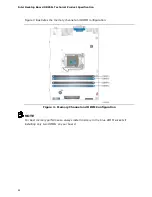
NOTE
Computer systems that have an unshielded cable attached to a USB port may not
meet FCC Class B requirements, even if no device is attached to the cable. Use a
shielded cable that meets the requirements for full-speed devices.
For information about
Refer to
The location of the USB connectors on the back panel
Figure 8, page 41
The location of the front panel USB headers
Figure 9, page 42


