


Balanced Technology Extended (BTX) Boxed Processor Specifications
116
Datasheet
8.2
Electrical Requirements
8.2.1
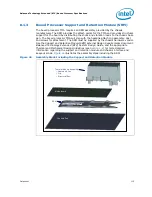
Thermal Module Assembly Power Supply
The boxed processor's Thermal Module Assembly (TMA) requires a +12 V power supply.
The TMA will include power cable to power the integrated fan and will plug into the 4-
wire fan header on the baseboard. The power cable connector and pinout are shown in
. Baseboards must provide a compatible power header to support the boxed
processor.
contains specifications for the input and output signals at the TMA.
The TMA outputs a SENSE signal, which is an open-collector output that pulses at a rate
of 2 pulses per fan revolution. A baseboard pull-up resistor provides V
OH
to match the
system board-mounted fan speed monitor requirements, if applicable. Use of the
SENSE signal is optional. If the SENSE signal is not used, pin 3 of the connector should
be tied to GND.
The TMA receives a Pulse Width Modulation (PWM) signal from the motherboard from
the 4
th
pin of the connector labeled as CONTROL.
Note:
The boxed processor’s TMA requires a co12 V supplied to pin 2 and does not
support variable voltage control or 3-pin PWM control.
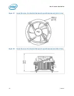
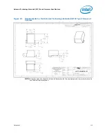
The power header on the baseboard must be positioned to allow the TMA power cable
to reach it. The power header identification and location should be documented in the
platform documentation, or on the system board itself.
shows the location of
the fan power connector relative to the processor socket. The baseboard power header
should be positioned within 4.33 inches from the center of the processor socket.
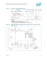
Figure 45.
Boxed Processor TMA Power Cable Connector Description
B
d P
P
C bl
Pin
Signal
1 2 3 4
1
2
3
4
GND
+12 V
SENSE
CONTROL
Straight square pin, 4-pin terminal housing with
polarizing ribs and friction locking ramp.
0.100" pitch, 0.025" square pin width.
Match with straight pin, friction lock header on
mainboard.
Содержание CORE 2 DUO E4000 - 3-2008
Страница 8: ...8 Datasheet ...
Страница 10: ...10 Datasheet ...
Страница 36: ...Electrical Specifications 36 Datasheet ...
Страница 38: ...Package Mechanical Specifications 38 Datasheet Figure 9 Processor Package Drawing Sheet 1 of 3 ...
Страница 39: ...Datasheet 39 Package Mechanical Specifications Figure 10 Processor Package Drawing Sheet 2 of 3 ...
Страница 40: ...Package Mechanical Specifications 40 Datasheet Figure 11 Processor Package Drawing Sheet 3 of 3 ...
Страница 46: ...Package Mechanical Specifications 46 Datasheet ...
Страница 100: ...Features 100 Datasheet ...
Страница 110: ...Boxed Processor Specifications 110 Datasheet ...
Страница 122: ...Debug Tools Specifications 122 Datasheet ...


