9
M L X 3 0 0 w a t t X e n o n L i g h t s o u r c e
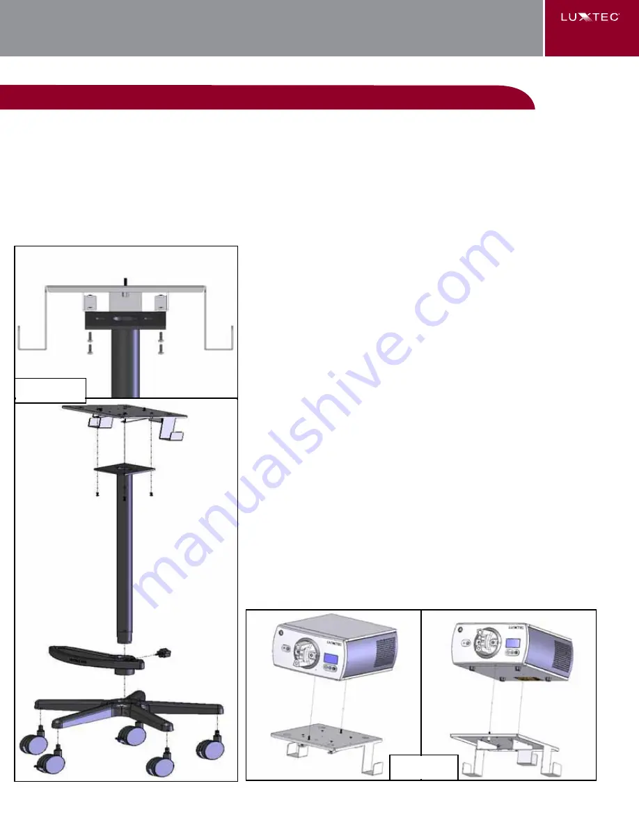
OPTIONAL fLOOR STAND ASSEMbLY
There are four (4) parts to the floor stand assembly:
(Figure 10).
(Phillips head screwdriver included for assembly)
1. Base with five (5) casters (2 locking)
2. one column with light source base plate
3. handle
4. MLX light source base
Floor stand assembly instructions:
1. with the handle positioned so that the Luxtec® logo is
properly aligned, slide the handle onto the column and
center the handle about 5 inches (13cm) below the light
source base plate. tighten handle screw to hold in place.
2. Insert assembled column into the base. Seat firmly.
3. attach the light source base onto the base plate
(Figure 10) with the four (4) screws provided, using the Phillips
head screwdriver provided.
4. secure the light source to base plate by aligning
the feet to the holes on the surface of the plate. tighten
the two screws on the bottom of the plate to the light source
(Figure 11).
Figure 11
Figure 10


