Intec ColorCut FB1150 Series Скачать руководство пользователя страница 12

Intec Printing Solutions - Manual for ColorCut flat bed series FB550 ..................................................................................... Page No: 12

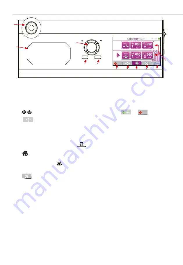
1.6 THE CONTROL PANEL (Overview of Navigation)


LED Display

  Displays Tool (Cut/Crease) information and menu parameters.

TOOL 1 -  SPEED / FORCE

 - Controls the speed and force of tool holder 1.

(Generally used to hold the blade for cutting).

TOOL 2 -  SPEED / FORCE

 - Control the speed and force of tool holder 2.

(Generally holds the creasing tool).
Tap on the screen to select each tool, use the HARD keys (left) to adjust values.

② 


(

Fan

Toggles the vacuum fan function on/off 

[


]

 /

[


]

③ 


 /

MOVE


  Takes  the Cutter [Of f-Line]  and enables your to move the tool 

carriage.   Used to set the start/origin for cutting and moving the 
carriage when placing sheets.   After moving the tool carriage, you 
must press ENTER twice if you want to define the position as a new 
ORIGIN.  The MOVE function also enables access to the Sensor light 
ON/OFF button 

 (enabling you to see the sensor position).

④ 


(

Home

HOME - Returns back to the main screen.

(When you use the MOVE function or scroll through the menu options, pressing 
the 

[


]

 (HOME)  key  leaves  the  screen  and  returns  to  the  HOME  screen.                                                                                               

(Default Home screen displays: Speed and Force - (for each Tool)

⑤ 


Menu


Scrolls through the machines menu settings/parameters.

Align Tool2 to Tool1 

- Sets the distance between tool holder 1 & tool holder 2.

Enabling you to align the CREASE to the CUT .  This is not the same as cutting  
in the correct position (see SENSOR OFFSET) in your software manual for that!.

Firmware Version

 - Displays the current installed version of firmwa e

.

Menu Mode

 - Displays the DEFAULT list (above) or ADVANCED list (below)


Work Mode


- Cut Plotter    - Enables both tool holder 1 and tool holder 2.


- Draw Plotter - Enables tool holder 1 (blade/cut ) only.


Scaling Factor

  - Scaling for the X direction and Y direction.


- Set at the factory, and typically does not need to be changed.


Factory Reset

 - Restores ALL factory default settings.

⑥ 

Test


Used to make a Test Cut to check whether the currently selected cutting 

conditions are compatible with the media loaded. Tool 2 creases a 45

O


rotated square (Like a diamond), then Tool 1 cuts a square around it.


Using a Test Cut you can check Blade Depth and pr essure for cutting 

and also confirm if the creasing Tool is perfectly aligned to Cutting Tool.

Offline

Enter

③ ④

Содержание ColorCut FB1150 Series

Страница 1: ...Intec Printing Solutions Manual for ColorCut flat bed series FB550 Page No 1 Dual Tool Flatbed Digital Die Cutters ColorCut FB550 Series Installation Setup Guide English Revision 2 0 0121...

Страница 2: ...Intec Printing Solutions Manual for ColorCut flat bed series FB550 Page No 2...

Страница 3: ...n steps 19 3 1 Assembling the Stand Cutter and Vacuum Pump 20 Component parts of the stand 20 Component parts of the vacuum fan pump 20 Assembly of stand 21 Assembly of vacuum fan pump 21 3 2 Software...

Страница 4: ...Intec Printing Solutions Manual for ColorCut flat bed series FB550 Page No 4...

Страница 5: ...Cut flat bed series FB550 Page No 5 1 1 Introduction 1 2 Specification 1 3 Unpacking overview 1 4 Identifying key features of your ColorCut Flatbed 1 5 Overview of the Control Panel Chapter 1 Chapter...

Страница 6: ...Intec Printing Solutions Manual for ColorCut flat bed series FB550 Page No 6...

Страница 7: ...orCut Pro cutter control software contains two parts i a pr ofessional direct plug in for Illustrator or Cor elDRAW enabling you to assign cut lines or paths created from Adobe Illustrator or CorelDRA...

Страница 8: ...vacuum control systems to provide media hold down during cutting Model Air Pump Vacuum Power Vacuum Control Accoustic Silencer ColorCut FB550 400W 400W Fixed Optional ColorCut FB750 750W 750W Fixed Ye...

Страница 9: ...ide the vacuum to hold down your media on the cutting table The stand pr ovides a perfect er gonomic working height for your cutter The final items found inside the accessories box include the power c...

Страница 10: ...ol 1 A dual ended Ball Bearing based tool to crease the media without breaking the fib es 2 crease widths are possible by using the dual ends Blades 3 1 x 30O Blade Yellow 1 x 45O Blade Red 1 x 60O Bl...

Страница 11: ...up down D Tool Holder 2 Holds the pen creasing tool and drives it up down E Beam Holds the tool carriage moves left right F Control Panel Used to set and use the cutter s various functions G Tool Rece...

Страница 12: ...pressing the HOME key leaves the screen and returns to the HOME screen Default Home screen displays Speed and Force for each Tool Menu Scrolls through the machines menu settings parameters Align Tool2...

Страница 13: ...DECREASE values on the LCD panel scr een Either for TOOL speed for ce control OR for changing menu settings or parameters The LCD screen will often indicate which key to use to incr ease or decrease...

Страница 14: ...Chapter 2 TOOLS for the Intec ColorCut Flatbed 2 1 Types of cutter blades 2 2 Blade Holder introduction 2 3 Replacing the blade 2 4 Blade length Adjustment Chapter 2...

Страница 15: ...ck media The sharply angled tip provides a longer cutting edge Suitable for cutting media from 0 5 to 1 5 mm thick For cutting sandblast rubber Creasing Blade Bearing based creasing ball double ended...

Страница 16: ...m of the blade holder 2 Adjust the amount of exposed visible blade tip to a suitable length by rotating C the Adjustment depth knob and then tighten the lock D 3 Press the push pin B to remove the bla...

Страница 17: ...he blade holder in your hand press down and cut a circle in the material Press down using a moderate amount of force while you cut the circle You will not be able to cut through the second sheet of pa...

Страница 18: ...assembly 3 2 1 Stand components 3 2 2 Vacuum Pump components 3 3 1 Assembly of the stand and cutter 3 3 2 Connecting the Vacuum pump 3 4 Connecting and Power on the Cutter 3 4 1 Turning on the Cutter...

Страница 19: ...check in the software that the cutter can be seen Install the Blade Creasing and Pen Tools Turn your cutter on then calibrate first the Creasing tool position to the cutting tool Next refer to your Co...

Страница 20: ...Cutter and Vacuum Pump Component parts of the vacuum fan pump 1 Left side panel leg 2 Right side panel leg Component parts of the stand 3 Front cross member 4 Rear cross member 6 Castors x 4 free whee...

Страница 21: ...ing the black bolts to attach the cross members Then attach the other side panel using same method Screw the stand feet into the bottom of side panels Remove the Rubber feet from the base of Flatbed L...

Страница 22: ...ColorCut with no need to learn a new application Intec ColorCut Pr o Software for your Intec ColorCut Flatbed is supplied on the included CD however it may also be downloaded fr om our website http i...

Страница 23: ...ur PC configuration Windows 10 users may see a security warning appear as this is not a Microsoft application Do not worry this is perfectly normal Click more info The dialogue box will confirm the Ap...

Страница 24: ...lt the ColorCut Pr o plug in software will automatically install into Adobe Illustrator if it is installed on your computer If you have Cor elDraw then the Plug in for CorelDraw will also be installed...

Страница 25: ...ill appear on the LCD panel asking your to pr ess the ENTER key to continue 4 Next the Intec ColorCut Flatbed digital cutter will move the T ool Carriage F to the closest point as shown in the figu e...

Страница 26: ...he fact it was subsequently disconnected and won t reconnect again until you power cycle both devices Do not disconnect or connect the USB cable while you ar e cutting a job or while data is being tra...

Страница 27: ...t or change the Cutter Device Type skin that ColorCut Pro has been customised to match Depending on the current selection your main screen may look like 5a or 5b 2 Click the SETTINGS button to open th...

Страница 28: ...ush Check that you have cleared the SAFETY MESSAGE that appears at power on on the LCD panel of the cutter AND that the FB550 cutter is ON LINE If the connection to your cutter is successful then unde...

Страница 29: ...l into your Intec ColorCut Flatbed loosen the tool holder s thumb screw sufficiently to enable a blade holder creasing tool or calibration pen to be inserted up to its flange Tool holder Bracket to ho...

Страница 30: ...our cut position may be offset from the position on the sheet that you actually wish to cut Calibrations are only r equired upon first use and normally do not need to be carried out subsequently 3 5 1...

Страница 31: ...of the LCD control panel 5 Using the Left Right physical keys move the beam over the sheet of paper then using the Up Down keys move the Tool Carriage to the middle of the piece of paper With the Too...

Страница 32: ...eed to 300mm s and use the Left Right keys to set the Force to 960 g The press the ENTER key to accept the settings 7 Set the appropriate pressure for the Calibration Pen Tool not too much pressure or...

Страница 33: ...ess the HOME tab key and continue to section 3 5 2 Calibrating the Sensor Offset If they ar e not aligned perfectly continue as detailed below to adjust the alignment 14 Press the MENU Tab button on t...

Страница 34: ...mputers or re install your computer you will need to perform the calibration again To make calibration easy ColorCut Pro can automatically perform the calibration for you using the PEN CALIBRA TION TO...

Страница 35: ...ys move the beam over the sheet of paper then using the Up Down keys move theTool Carriage to the middle of the piece of paper 7 With the Tool Carriage in the middle of the sheet of paper press the EN...

Страница 36: ...ro application will be displayed 3 5 2 Calibration of the Sensor Offset to the Cutting Blade B C 9 The Vision Sensor Offset 1 setting provides the ability to calibrate the sensor offset automatically...

Страница 37: ...de holder Remembering SET THE BLADE DEPTH EXPOSURE TO THE LEAST AMOUNT POSSIBLE Less is MUCH better than more 3 Refer to section 3 4 Installing the Tools Install the Blade holder in to the Tool carria...

Страница 38: ...e Start at approx 360 g When cutting through your media the aim is to have the smallest amount of blade out as possible to achieve the cut and use a reasonable force For 350micron card 15pt we would s...

Страница 39: ...heck you have not got too much blade exposed On labels a low pressure is OK because you are not cutting the backing material However in Card cut through applications if the blade cuts through at under...

Страница 40: ......

Страница 41: ......

Страница 42: ......

Страница 43: ......

Страница 44: ...Intec Printing Solutions Ltd Unit 11B Dawkins Road Industrial Poole Dorset BH15 4JP Tel 44 1202 845960 Web www intecprinters com email support intecprinters com...

Отзывы: