Inta Nulo CB10032CP Скачать руководство пользователя страница 15

© Intatec Ltd 2017

14

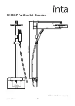
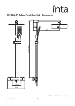
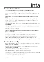
Fixed Riser Rail - Installation

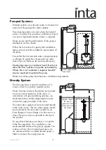
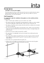
Fit the shower valve and finish tiling the wall prior to installing the shower riser.

Ensure the overhead arm projection does not exceed the shower tray.

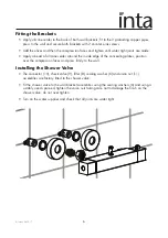
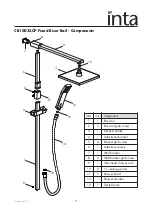
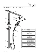
Assemble the adjustment piece (6) into the top of the riser rail (1) ensuring both seals are fully 
inserted.

Slide the handset holder (3) over the adjustment piece (6) and lock into position on the riser  
rail (1).

Slide the adjustment bracket (4) over the adjustment piece and set to the required height.

Once the height has been set lock the bracket into place by tightening the grub screws (5) 
using a suitably sized Allen key.

Locate the overhead shower arm (9) onto the adjustment piece (6) and the wall bracket (7) into 
the overhead arm.

Fit the riser rail assembly to the shower valve and using a suitable method mark round the wall 
bracket (7) onto the wall.

Remove the riser rail and wall bracket.

Position the wall bracket onto the wall within the markings and using the hole as a template, 
drill a 6mm diameter hole.

If drilling into ceramic tiles use a ceramic bit.

To avoid cracking ensure the wall plug is pushed all the way behind the ceramic tile.

Using the screw provided secure the wall box firmly to the wall. This is the main fixing 
screw for the riser and shower so must be held securely by the plastic plug in the wall.

If the wall is plaster board or soft building block use special wall  plugs obtainable from most DIY
stores.

Fixed Riser Rail - Assembly

Attach the shower head (11) to the shower arm using a ½” sealing washer (10) to create a water
tight seal onto the riser rail assembly.

Re-assemble the riser rail to the shower valve and over head arm (9) onto the wall bracket 
(7) ensuring the riser rail is vertical.

Tighten the two wall bracket grub screws (8) to secure the riser rail.

Secure the grub screw (2) at the bottom of the riser rail to fix in position.

   Connect the shower handset (12) to the flexible hose (13) and the hose to the bottom outlet of the
   shower valve, ensure the ½” sealing washers (10) are fitted. 

   Turn on the water supply and check joints for leakage.

Содержание Nulo CB10032CP

Страница 1: ...tion as accurate as possible We cannot accept any responsibility should it be found that in any respect the information is inaccurate or incomplete or becomes so as a result of further developments or...

Страница 2: ...d at a safe temperature to suit the users The shower is pre set using ideal conditions to 38 C at the stop with a manual push button override to 46 C can be re set to suit site conditions or user pref...

Страница 3: ...t Temperature 85 C Max Inlet Pressure Dynamic 5 bar Pre Set Factory Temp Setting 38 C Min Operating Pressure Dynamic 0 4 bar Temperature Stability 2 C Max Unbalanced Pressure Ratio 5 1 Min Temp Differ...

Страница 4: ...her than the hot supply we recommend that a separate pressure reducing valve is fitted to the cold supply as close as possible to the shower valve and with no draw off points between it and the shower...

Страница 5: ...lt the pump manufacturer s installation requirements Gravity System The drawing shows a typical installation of a shower valve on a gravity supplied system Please note the minimum head pressure requir...

Страница 6: ...plaster or plaster board should all be considered when routing the hot and cold supply pipes The valve requires the supply pipes and wall brackets to have 150mm centres and sufficient copper pipe mus...

Страница 7: ...inside edge of the concealing plates position over the compression faces and press firmly to the wall Installing the Shower Valve The connector 10 check valve 9 filter 8 sealing washer 6 and union nu...

Страница 8: ...ow control 1 and allow the outlet temperature to stabilise from the bottom outlet Temporarily refit the control knob bush 8 and control knob 6 and using a digital thermometer it is possible to increas...

Страница 9: ...have a high quality finish and should be treated with care An occasional wipe with a mild washing up liquid on a soft damp cloth followed by a thorough rinsing is all that is required The nozzles in t...

Страница 10: ...maximum showering temperature is too hot or when set to hot water runs to cold Check the commissioned maximum temperature of the shower valve Check the connections to the valve have not been made in r...

Страница 11: ...Intatec Ltd 2017 10 NOTE drawing for illustration purposes only CB10032CP Fixed Riser Rail Dimensions 150 Ctrs 264 722 to 952 55 410 71 200...

Страница 12: ...0 Item Qty Component 1 1 Riser rail 2 1 Riser rail grub screw 3 1 Handset holder 4 1 Adjustment bracket 5 4 Bracket grub screw 6 1 Adjustment piece 7 1 Wall bracket 8 2 Wall bracket grub screw 9 1 Ove...

Страница 13: ...Intatec Ltd 2017 12 CB10036CP Deluxe Fixed Riser Rail Dimensions NOTE drawing for illustration purposes only 150 Ctrs 264 55 410 250 722 to 952...

Страница 14: ...m Qty Component 1 1 Riser rail 2 1 Riser rail grub screw 3 1 Handset holder 4 1 Adjustment bracket 5 4 Bracket grub screw 6 1 Adjustment piece 7 1 Wall bracket 8 2 Wall bracket grub screw 9 1 Over hea...

Страница 15: ...ithin the markings and using the hole as a template drill a 6mm diameter hole If drilling into ceramic tiles use a ceramic bit To avoid cracking ensure the wall plug is pushed all the way behind the c...

Страница 16: ...ure the conditions of use are appropriate for the valve Introduction The thermostatic shower valve has been specifically designed and manufactured to meet the requirements of BS EN1111 1999 and TMV2 T...

Страница 17: ...99 and also be aware of their responsibility and duty of care to ensure that all aspects of the installation comply with the regulations It has been brought to our attention that flushing water system...

Страница 18: ...e s to within the limits as quoted previously 8 Any thermostatic shower valve must be fitted with a back flow prevention device such as check valves to prevent the cross contamination of supplies The...

Страница 19: ...eratures are established before any attempt to commission 4 Once the supply temperatures are stable and the normal operating conditions are established the shower valve can be commissioned The followi...

Страница 20: ...g performance checks shall be carried out 1 Measure the mixed water temperature at the outlet 2 Carry out the cold water supply isolation test by isolating the cold water supply wait for five seconds...

Страница 21: ...Intatec Ltd 2017 20 Notes...

Страница 22: ...Intatec Ltd 2017 21 Notes...

Страница 23: ...Intatec Ltd 2017 22 Notes...

Страница 24: ...n Staffordshire ST18 0PF Tel 01889 272 180 Fax 01889 272 181 email sales intatec co uk web www intatec co uk E O E 11 08 17 To activate your product warranty please visit www intatec co uk and click o...

Отзывы: