Inspire HYP1 Скачать руководство пользователя страница 4

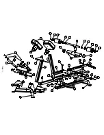
PARTS & HARDWARE LIST 
 

Item # 

Description 

Part Number 

Quantity 

Front Foot Tube Assembly 

GM582-200-001 

Stabilizer Assembly 

GM582-100-001 PZ 

Front Support Tube Assembly 

GM582-270-001PZ 

Handle Assembly 

GM582-250-001PZ 

Adjustment Tube Assembly 

GM582-230-001PZ 

Pivot Tube Assembly 

GM582-210-001PZ 

Lower Adjustment Tube Assembly 

GM582-220-001PZ 

Upper Adjustment Tube Assembly 

GM582-240-001PZ 

Leg Rest Assembly 

GM582-260-001PZ 

10 

Foot Roller 

GM582-861-001PZ 

11 

Back Pad Assembly 

GM582-401-001PZ 

Hardware Pack 

GM582-891-007 

12 

Lock Nut M12 

0110-712-008 

13 

Hex Bolt M12x110 

0111-012-018 

14 

Spacer 1 

GM582-561-010 

16 

Hex Screw M18x15 

0113-210-208 

17 

Handle End Cap 

GM870-561-016 

20 

Hex Set Screw M5x4 

0113-805-049 

21 

Hex Bolt M12x95 

0111-012-958 

22 

Hex Bolt M10x25 

0111-010-258 

24 

Rubber End Cap 2 

GM582-881-005 

25 

Rubber End Cap 1 

GM582-881-004 

26 

Pop-Pin 

GM851-881-010 

27 

Hex Bolt M10x45 

0113-210-458 

28 

Wheel Roller 

AB83-021-26 

29 

Flat Washer φ10 

0110-010-008 

30 

Lock Nut M10 

0110-710-008 

31 

Seat Insert 

GM468-881-003 

32 

Spacer 2 

GM582-561-009 

33 

Hex Bolt M10x60 

0111-010-608 

34 

Upper Adjustment Sleeve 

GM582-881-002 

35 

End Cap 

GM578-881-003A 

36 

Tightening Screw 

GM582-881-001 

37 

Flathead Screw M10x25 

0113-210-258 

38 

Foam Stick End Cap 

GM870-561-017 

39 

Flat Washer φ12 

0116-012-008A 

40 

Plastic Washer 

GM024-881-002 

41 

Foam Stopper 

GM582-281-001 

43 

Tap Bolt ST4.2x15 

0114-142-15 


Page 2 

Содержание HYP1

Страница 1: ...www inspirefitness com RECORD SERIAL NUMBER HERE by Health In Motion LLC Feb 2015 ASSEMBLY OPERATION MANUAL ...

Страница 2: ...on Description Page Important Safety Instructions 1 Parts List 2 Exploded Diagram 3 Assembly Instructions 4 Decal Reference 13 Decal Placement 14 General Maintenance Information 15 Maintenance Schedule 16 Limited Warranty 17 ...

Страница 3: ...ails Use this hyper extension for its intended purpose as described in this Operation Manual Make sure bystanders are at least 5 feet away from the hyper extension while it is in use Keep children away from the hyper extension at all times Keep the hyper extension away from walls and clear of any obstructions and furniture Stop immediately if you experience shortness of breath pain or dizziness du...

Страница 4: ...r 1 GM582 561 010 2 16 Hex Screw M18x15 0113 210 208 2 17 Handle End Cap GM870 561 016 2 20 Hex Set Screw M5x4 0113 805 049 4 21 Hex Bolt M12x95 0111 012 958 22 Hex Bolt M10x25 0111 010 258 24 Rubber End Cap 2 GM582 881 005 1 25 Rubber End Cap 1 GM582 881 004 1 26 Pop Pin GM851 881 010 2 27 Hex Bolt M10x45 0113 210 458 2 28 Wheel Roller AB83 021 26 2 29 Flat Washer φ10 0110 010 008 30 Lock Nut M10...

Страница 5: ...9 29 29 33 33 27 29 28 29 30 21 39 12 39 34 12 39 14 39 13 3 1 12 12 12 39 39 39 12 39 21 21 21 21 11 11 11 11 6 12 12 39 39 39 39 21 21 4 5 36 31 31 26 12 39 32 39 17 16 16 17 21 2 7 27 29 28 30 29 8 43 43 41 40 40 41 39 39 39 39 20 20 20 20 24 25 Page 3 32 ...

Страница 6: ...1 21 39 39 39 39 12 12 1 2 PAGE 4 Step 1 Combine the Front Foot Tube Assembly 1 and the Stabilizer Assembly 2 A using 2 Hex Bolts M12x95 21 4 Flat Washers ɸ12 39 and 2 Lock Nuts M12 12 Hand Tighten Only ...

Страница 7: ...vot Tube Assembly 6 to the Stabilizer Assembly 2 using 1 Hex Bolt M12x95 21 2 Flat Washers ɸ12 39 and 1 Lock Nut M12 12 Make sure the Hex Bolt M12x95 21 goes through Spacer 2 32 inside the Pivot Tube Assembly 6 TIGHTEN HARDWARE FROM THIS STEP ONLY ...

Страница 8: ...6 7 26 PAGE 6 Step 3 Loosen the Pop pin 26 and insert the Lower Adjustment Tube Assembly 7 into the A Pivot Tube Assembly 6 ...

Страница 9: ...Assembly 5 to the Lower Adjustment Tube Assembly 7 usinge 1 Hex Bolt M12x95 21 2 Flat Washers ɸ12 39 and 1 Lock Nut M12 12 Make sure the Hex Bolt M12x95 21 goes through Spacer 2 32 inside the Lower Adjustment Tube Assembly 7 TIGHTEN HARDWARE FROM THIS STEP ONLY ...

Страница 10: ...0 38 37 9 PAGE 8 Step 5 Attach the Aluminum Cap 38 Foot Roller 10 Plastic Washer 40 and A Foam Stopper 41 to the Leg Rest Assembly 9 using 1 Flathead Screw M10x25 37 Repeat for both sides TIGHTEN HARDWARE FROM THIS STEP ONLY ...

Страница 11: ...s M10x60 33 4 Flat Washers ɸ10 29 and 2 Lock Nuts M10 30 Unscrew the Pop pin and insert the Upper Adjustment Tube Assembly 8 into B Adjustment Tube Assembly 5 Note The Tightening Screw 36 needs to be loosened in order for the Upper Adjustment Tube Assembly 8 to go into the Adjustment Tube Assembly 5 TIGHTEN HARDWARE FROM THIS STEP ONLY ...

Страница 12: ...9 39 39 21 21 12 12 1 3 PAGE 10 Step 7 Attach the Front Support Tube Assembly 3 to the Front Foot Tube Assembly 1 using A 2 Hex Bolts M12x95 21 4 Flat Washers ɸ12 39 and 2 Lock Nuts M12 12 HAND TIGHTEN ONLY ...

Страница 13: ...s M12x95 21 4 Flat Washers ɸ12 39 and 2 Lock Nuts M12 12 Attach the Handle Assembly 4 to the Front Support Tube Assembly 3 using 1 Hex B Bolt M12x110 13 2 Flat Washers ɸ12 39 and 1 Lock Nut M12 12 Make sure the Hex Bolt M12x110 13 goes through Spacer 1 14 inside the Front Support Tube Assembly 3 TIGHTEN ALL HARDWARE FROM STEP 1 STEP 7 STEP 8 ...

Страница 14: ... 12 Step 9 Attach the Back Pad Assembly 11 onto the Handle Assembly 4 using 2 Hex Bolts A M10x25 22 and 2 Flat Washers ɸ10 29 Repeat for both sides Note Back Pads can be oriented in either direction The default orientation is shown above TIGHTEN HARDWARE NOW ...

Страница 15: ...DECAL REFERENCE Page 13 ...

Страница 16: ... Warning Pinch Point Side of the plate Warning Pinch Point Bottom of the Assembly Warning Label Checklist on the reverse side Serial Number PAGE 14 DECAL PLACEMENT ...

Страница 17: ...ing on the orthopedic pads these pads have a special density that takes shape to objects and small objects will leave imprints in the surface that may take time to come out Regularly inspect product for loose hardware Do not use or store equipment outdoors Locate and familiarize yourself with all warning decals on the hyper extension Replace damaged or worn upholstery immediately Page 15 ...

Страница 18: ... Spring Clips Swivels Weight Stack Pins WEEKLY Clean Upholstery WEEKLY Inspect Accessory Bars and Handles 3 MONTHS Inspect All Decals 3 MONTHS Inspect All Nuts and Bolts Tighten if Needed 3 MONTHS Inspect Anti Skid surfaces 3 MONTHS Clean and Wax All Glossy Finishes YEARLY Page 16 ...

Страница 19: ...sociated with transportation of the Product In addition you are responsible for insuring any Product shipped or returned You assume the risk of loss during shipment You must present Health In Motion with proof of purchase documents including the date of purchase Model and Serial Number Any evidence of alteration erasing or forgery of proof of purchase documents will be cause to void this Warranty ...

Отзывы: