


5
8
9
33
33
29
29
29
29
30
30
36
PAGE 9
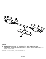
Step 6
Attach the Leg Rest Assembly (9) to the Upper Adjustment Tube Assembly (8) using
A
2- Hex Bolts M10x60 (33), 4- Flat Washers
ɸ
10 (29) and 2- Lock Nuts M10 (30)
Unscrew the Pop-pin and insert the Upper Adjustment Tube Assembly (8) into
B
Adjustment Tube Assembly (5).
Note: The Tightening Screw (36) needs to be loosened in order for the Upper
Adjustment Tube Assembly (8) to go into the Adjustment Tube Assembly (5)
TIGHTEN HARDWARE FROM THIS STEP ONLY.
Содержание HYP1
Страница 15: ...DECAL REFERENCE Page 13 ...