8
Installation Instructions
PLUMBING (cont.)
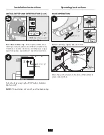
ADJUSTING WATER TEMPERATURE
NOTE:
It may be necessary to adjust the mixing valve to
set the appropriate water temperature.
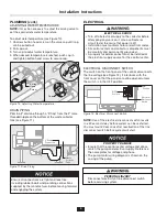
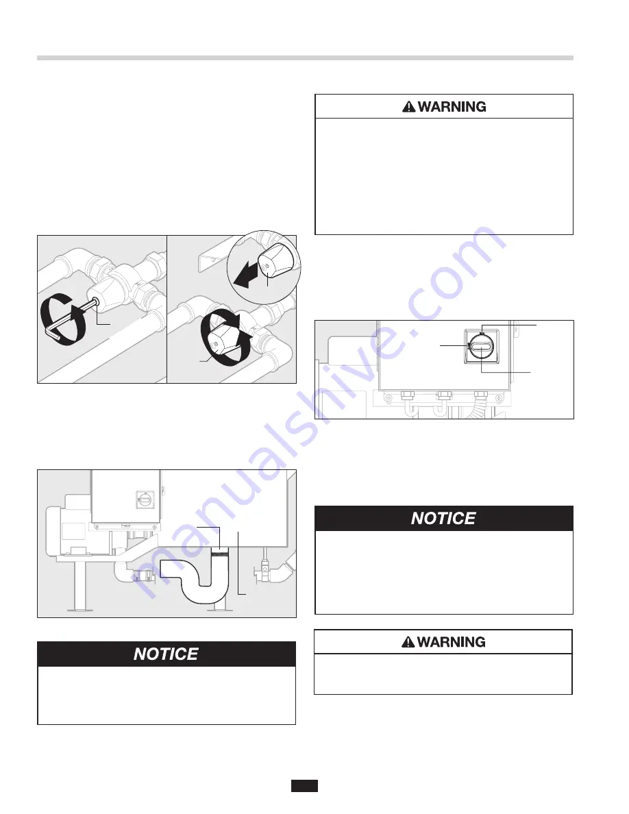
To adjust water temperature (see Figure 10):
1. Unscrew button head screw on the valve cap until cap
can be pulled out.
2. Pull cap out.
3. Turn cap to adjust water temperature.
4. When desired temperature is reached, push cap in
and tighten button head screw to secure cap.
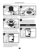
DRAIN PIPING
Plumb a 2" drainline through a “P-trap” from the 2" male
threaded nipple on the bottom of the waste collector
tank (see Figure 11).
ELECTRICAL
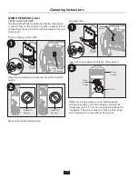
ELECTRICAL DISCONNECT SWITCH
The switch on the front panel of the control disconnects
the line voltage (see Figure 12). It interlocks with the
front cover so that the panel cannot be opened unless
the switch is in the OFF position.
NOTE:
Use of the electrical disconnect switch results
in a 30 second delay before system can be restarted.
You must wait 30 seconds after reactivation of the line
disconnect switch before system will start.
Ensure all connections are tight and leak free,
including rubber boots and plumbing connections
supplied by the manufacturer, before moving forward
and engaging the system.
1
3
3
2
Button
Head
Screw
Cap
Cap
Figure 10. Adjusting Water Temperature
2" Drain
Connection
Waste
Collector
Tank
Figure 11. Drain Piping
PROPERTY DAMAGE
• Ensure that the control center voltage and phase
match the pump and electrical supply. Reference
the nameplates for voltage and phase.
• The pump motor wiring diagram is shown on the
casing of the pump.
PERSONAL INJURY
Disconnect electricity at line disconnect switch
before servicing system.
ELECTRICAL SHOCK
• Turn off all electrical supply to the collector before
attempting any work on it. Use a voltmeter or
circuit tester to ensure that power is off.
• Installation must conform to local electrical codes.
• All control centers and collector components must
be carefully and permanently grounded.
• A properly fused disconnect must be installed at
the electrical supply source for the control center.
ON
Position
OFF
Position
Electrical
Disconnect
Switch
Figure 12. Electrical Disconnect Switch


