SS-GM-02 Owner’s Manual
Document: OM-236 Version Code: A
Date: May 06, 2020 Date: Feb 05, 2021
© Copyright 2021 InPower LLC
Page
6 of 8
InPower LLC
8311 Green Meadows Drive
Lewis Center, Ohio 43035 USA
740-548-0965
www.InPowerLLC.com
2.4 Mounting the SS-GM-02
It is suggested the mounting of the SS-GM-02 module be on the frame rail on the
backside of the GM PTO Controller Bracket. There are holes in this bracket that will
facilitate mounting. These will accommodate #10 mounting hardware. This location
will insure that there is enough wire to plug into the GM PTO Upfitter Connector and
into the SS-GM-02.
There are blunt cut wires provided for the interface to the PTO itself. The Control of
the PTO is performed by the Group 3 wire bundle shown in the
SS-GM-02 Harness
START/STOP/High Idle. The PTO-CTL Light Green Wire and White/Black GND wire
together control the engagement of the PTO and the PTO-FB provides Feedback that
the PTO is on and running. This PTO-FB Signal (Group 3 Yellow PTO-FB and +12V
Yellow/Red) is based on PTO Pressure indicating that the PTO is on and functioning
properly. Both of these need to have the PTO specific connectors connected to the
provided blunt cut wires.
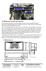
Overview of Framerail PTO Controller and
PTO Upfitter Connector
Looking up from underneath
Location of PTO
Upfitter Connector
Suggested Location
for SS-GM-02
GM PTO
Controller


