PARA
METER
DESCRIPTION
DEFAULT
DISPLAY
PARA
METER
DESCRIPTION
DEFAULT
DISPLAY
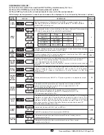
ALARM
INHIBIT
This parameter can be used to inhibit (suppress) the Alarm activation upon power-up
conditions by setting the parameter value to ‘YES”. From Power-up, the Alarm
system remains disabled until PV is found with in the limits.
If Alarm activation is desired even under Power-up condition, Set this parameter
value to ‘NO’.
NO
ALARM
LOGIC
DIRECT
If this parameter is set as ‘Direct’, Relay/SSR energizes under Alarm condition &
remains De-energized otherwise. ‘Direct’ setting is generally used for Audio/Visual
Alarm Output.
If this parameter is set as ‘Reverse’, Relay/SSR De-energizes under Alarm condition
& remains energized otherwise. ‘Reverse’ setting is generally used for tripping the
process under Alarm condition.
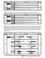
ALARM
ACK.
AUTO
Once Alarm is activated, it can be de-activated either by pressing UP key or when PV
falls within the alarm limits.
Once Alarm is activated, it remains activated until manually acknowledged by UP
key.
Once Alarm is activated, user has following three options to de-activate it.
When PV falls within the programmed limits, Alarm will be de-activated automatically.
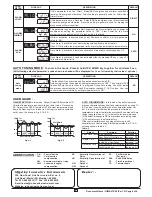
ON-OFF ACTION:
In this mode, Output (Relay/SSR) remains ON
till actual temperature reaches to the set point value. On reaching
SP, Output turns OFF & remains OFF till actual temperature drops
down (in Heat Logic) or raises (in Cool Logic) equal to hysterisis
set by user. (As shown in Fig. 3.1 & 3.2).
USER GUIDE :
(All following selected parameter’s code shown in shaded will be displayed for 1 sec. followed by their values / options)
HEAT LOGIC/ON-OFF
TIME
TEMP ( C)
0
HYSTRISIS
SP
ON
ON
ON
AMB
O/P
OFF
OFF
TIME
COOL LOGIC / ON OFF
O/P
O/P
TEMP ( C)
0
AMB
HYSTERISIS
ON
ON
ON
SP
OFF
OFF
Table: 3
Adjust
Proportional Band
Integral Time
Derivative Time
Slow Response
Over Shoot or Oscillations
Slow Response
Instability or Oscillation
Slow Response or Oscillation
High Over Shoot
Decrease PB
Increase PB
Decrease Int
Increase Int
Decrease Dt
Increase Dt
Symptom
Solution
AUTO TUNING MODE :
In this mode, Controller learns the
process characteristics by itself and calculates the required P, I
& D values. It can be performed at any time after power ON
but, it is best to start it when the process is at Ambient
temperature in order to minimize overshoot & undershoot. Auto
tuning is applied in case : (1) Initial set up for a new process.
(2) Substantial change in SP from previous auto tuning value.
(3) Control accuracy is not satisfactory.
If the control performance by using auto-tuning is still
unsatisfactory, User can apply further adjustments of P, I & D
values as shown in table 3.
ABBREVIATION :
NC
: Normally Close terminal of
Relay
NO
: Normally Open terminal of
Relay
OP1
: Output 1
OP2
: Output 2
C.A.
: Control Action
CJC
: Cold junction
compensation
CM
: Common terminal of relay
LWC
: Lead wire (Length)
compensation
SP
: Set Point Value
(Set temp.)
SSR
: Solid State Relay
T.P.
: Time Proportional
T/C
: Thermocouple
Fig: 3.1
Fig: 3.2
Auto
tuning
mode
This function will be executed only if selected control action is PID.
Auto-tuning function is enabled by setting this parameter to ‘YES’. The decimal of LSB
flashes till Auto tuning function is in progress. During Auto-tuning, Controller learns
the process characteristics by itself & calculates required P, I & D values. User can
cancel or abort this feature by setting this parameter to ‘NO’.
NO
AUTO TUNING MODE :
To enter in this mode, Press & hold UP & DOWN key together for minimum 3 sec.
338, New Sonal Link Service Ind. Est. no.2 ,
Link Road, Malad (W), Mumbai - 400064.
Tel: 022-66939916/17. Fax: 022-66939918
E-mail:[email protected] ;
Website: innovativeinstrument.com
: Innovative Instruments
Mfgd by
: -
Dealer
6
Document Name : OIM AI-7X42 (Ver 1.2) Page 6 of 6


