background image


Page 33 of 41 


iFleetONE™ Terminal Installation Manual  

REGISTERED 

Steady 

Amber


Attempting network registration 

Blinking 

Amber


Ready for Voice only. 

Blinking 

Green


Ready for Data only. 

Steady 

Green


Ready for all (Voice and Data). 

Steady 

Red


Network failure / Registration error. 

No light (Off) 

No network service. 

DATA ACTIVE 

Steady 

Amber


Activating data connection. 

Steady 

Green


Data connection is ready. 

Steady 

Red


Data activation failure 

No light (Off) 

No data connection. 


1.11  Settings on Web Console 

1.11.1  Activating on Web Console 


Open the web browser (for example: Internet Explorer, Google Chrome or Firefox.)  


and type 

http://192.168.1.35/

 in the Address field. 


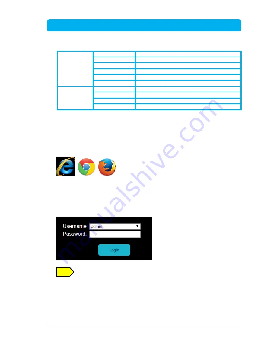
Username and Password will be prompted.  
 

Default Username   : 

admin


Password    

1234


On the first time use of the terminal, you will be asked to enter a new password. 


Click “

Login

” after entering the Username and Password. 


NOTE 

Содержание wideye iFleetONE

Страница 1: ...Satellite Terminal Installation Manual Revision 2 0...

Страница 2: ...y or representation as to the accuracy completeness or fitness for purpose or use of the information Addvalue shall not be liable for any loss or damage of any kind including indirect or consequential...

Страница 3: ...___________18 1 5 4 Obstruction_____________________________________________________20 1 5 5 Antenna Mast___________________________________________________21 1 5 6 Installing the Antenna Unit _______...

Страница 4: ...__________37 A 2 ADU Hole Pattern Cut out Holes ____________________________________38 A 3 BDU Outline Dimensions and Weight _________________________________39 A 4 Optional Primary Handset Outline Di...

Страница 5: ...cause harmful interference to radio communications However there is no guarantee that interference will not occur in a particular installation If this equipment does cause harmful interference to radi...

Страница 6: ...ion is subject to the following two conditions 1 This device may not cause interference and 2 This device must accept any interference including interference that may cause undesired operation of the...

Страница 7: ...upgrade process of the CE RED tests Mobile Earth Stations MES 1668 1670 MHz is under restricted usage under ECC Decision ECC DEC 04 09 for EU Countries User Operator shall check with local Radio Spec...

Страница 8: ...those areas of the UE that are marked with this symbol otherwise it may result in injury Antenna Radiation Warning and Distance to other Radiation Equipment For safety reasons all personnel must keep...

Страница 9: ...t be operated in the presence of flammable gases or fumes as well as any explosive atmosphere Operation of any electrical equipment in such an environment constitutes a definite safety hazard Obtainin...

Страница 10: ...t the distributor or manufacturer for instructions and assistance Any modifications or attempts to open the devices by non authorized personnel will void the warranty Contents in this manual are subje...

Страница 11: ...ncluding but not limited to the implied warranties of merchantability and fitness for a particular purpose Trademarks All trademarks marks names or product names referenced in this publication are the...

Страница 12: ...en areas represent the voice and data services and they are known as the Home Region area The area outside the home region area is known as Out of Region which supports only voice service including 50...

Страница 13: ...etONE ADU iFleetONE BDU Router Computer External Devices Above Deck Unit To be installed in an exposed area Below Deck Unit To be installed in protected area AC DC Power Supply Unit RJ45 GPIO Interfac...

Страница 14: ...meter Antenna Cable FLV2 0AN00 01 iFleetONE Optional Accessories Description Order Code Wideye iFleetONE Primary Handset SLF1 0PH00 01 Power Supply 240W AC DC DIN Rail 24V DC 10A SKP150 ADPS Antenna...

Страница 15: ...andset with a cradle is an optional accessory 1 2 Above Deck Equipment The ADU is a 3 axis controlled antenna unit which is self tracking The radome covers the antenna unit which is comprised of Anten...

Страница 16: ...power supply input It supplies power to the ADU via a single RF coaxial antenna cable 1 4 Optional Primary Handset with Cradle The wired Primary Handset has a colour liquid crystal display LCD and key...

Страница 17: ...free of severe vibration and shock and heat and smoke from the funnel More guidelines will be detailed in the next sections 1 5 2 Radiation Hazard Radio waves can pose a hazard to the human body Safe...

Страница 18: ...minimum distance between a radar and the antenna unit due to different type of radars in terms of power radiation pattern and operating frequency band The antenna unit is recommended to be at least 15...

Страница 19: ...e with the performance of the antenna and also damage the antenna if placed too close The table below gives guidelines for the minimum distance between the antenna and HF and VHF transmitters Antenna...

Страница 20: ...enna moves in azimuth 360 and in roll and pitch down to 15 to ensure constant tracking even in heavy seas Any obstructions within this arc can cause performance degradation of the signal quality The a...

Страница 21: ...e antenna mounted in a suitable mast is illustrated as below Recommendations of the antenna mast include The mast should provide the internal hole for the installation of the antenna coaxial cable The...

Страница 22: ...he Antenna Unit The antenna unit should be carefully unpacked and checked for any damage The procedure for the installation of the antenna unit is as follows Attach the coaxial cable to the RF connect...

Страница 23: ...t Cable 1 x DC Power Cable 1 x Inmarsat 505 laminated card 1 x Wi Fi Antenna Hardcopy Quick Start Guide CD ROM Soft User Manual Cable Support Kit The following important notes are to be followed for t...

Страница 24: ...U Remove the 2 screws of the front mounting bracket Mount the cable support item on the bottom of the BDU Replace and tighten the same 2 screws to secure the cable support item The BDU can be installe...

Страница 25: ...Page 25 of 41 iFleetONE Terminal Installation Manual Using the holes of mounting brackets and four suitable M4x12mm self tapping or machined screws so that the BDU is secured to the selected surface...

Страница 26: ...d with the M5 x 12mm self tapping screws The procedure for installing the cradle is as follows a Separate the handset from the cradle and remove the plastic cover of the cradle b Position the cradle o...

Страница 27: ...ONE Terminal with the cables 12V 24V DC Input from Vessel s power distributor Earth cable to vessel s hull Computer 1 5m Ethernet LAN Category 5 Cable 1 8m DC Power Cable Antenna Unit ADU 15 meter Ant...

Страница 28: ...tput ports GPS and GPIO 1 8 1 GPS Output Connector The BDU has a GPS output RS 232 serial connector for outputting the GPS data in NMEA0183 format RS 232 Output Pinout Pin No Signal Pin 3 TX Pin 2 RX...

Страница 29: ...he antenna unit s transmitter 3 PDP_ON OFF To enable disable the data connection 4 BUZZER To enable external ringer buzzer for an incoming call 5 GND To provide grounding for the whole system 6 REMOTE...

Страница 30: ...rt grease and metal oxide at the connection point to the hull GETTING STARTED ON THE SYSTEM 1 9 Installing the SIM card The system requires a Fleet One service SIM card to access the Inmarsat network...

Страница 31: ...Page 31 of 41 iFleetONE Terminal Installation Manual Push the SIM card gently into the slot until it is locked in place Close the SIM card protective cover SIM CARD...

Страница 32: ...ERMINAL ANTENNA and REGISTERED to turn green LED Name Status Meaning TERMINAL Steady Amber Terminal BDU is powering up Steady Green Terminal BDU has powered up successfully Steady Red Terminal BDU has...

Страница 33: ...ivating data connection Steady Green Data connection is ready Steady Red Data activation failure No light Off No data connection 1 11 Settings on Web Console 1 11 1 Activating on Web Console Open the...

Страница 34: ...gistration with the BDU s LED indicators TERMINAL ANTENNA and REGSITERED in green the terminal will be ready for normal operation 1 11 2 Activating a PDP Context To activate the PDP context for browsi...

Страница 35: ...Terminal Installation Manual 1 11 3 Deactivating a PDP Context To deactivate the PDP context for browsing the internet or other IP connectivity click Deactivate Data Connection The BDU LED indicator D...

Страница 36: ...BDU Below Decks Unit DC Direct Current FTP File Transfer Protocol GPS Global Position System GPIO General Purpose Input Output IP Data Internet Protocol Data NAT Network Address Translation PAT Port...

Страница 37: ...Page 37 of 41 iFleetONE Terminal Installation Manual APPENDIX A OUTLINE DRAWINGS A 1 ADU Outline Dimensions and Weight Weight 3 2 kg Dimensions are expressed in terms of mm...

Страница 38: ...Page 38 of 41 iFleetONE Terminal Installation Manual A 2 ADU Hole Pattern Cut out Holes Dimensions are expressed in terms of mm...

Страница 39: ...al Installation Manual A 3 BDU Outline Dimensions and Weight A 4 Optional Primary Handset Outline Dimensions Weight 3 1kg Dimensions are expressed in terms of mm Weight 430g including cradle Dimension...

Страница 40: ...data connection switch is ACROLECTRIC SWITCH P N C1350XBAAA which is a non illuminated rocker switch This item is not included in the packaging list The connection diagram is illustrated below The ste...

Страница 41: ...Page 41 of 41 iFleetONE Terminal Installation Manual 3 Connect the other end of these AWG 24 wires to the GPIO Adaptor s Pin 1 and 3 respectively 1 3...

Отзывы: