


1
2
3
4
5
6
Mounting Location
Disconnect Power
-
Plan the layout of the fixtures and ensure power wiring is routed
to all installation locations.
-
Place the wall switch to the "OFF" position. (Fig.1.)
-
Depending on which type of fuse box you have in your home:
-
A 3" or 4" junction box must be installed at each desired location
before installing the fixture.
Fig.2.
Place either the main (Master) switch to the "OFF" position,
cutting off power to your entire home OR turn off the individual
switch that provides power to where the fixture will be installed
l
Junction Box (Not included)
• 3" & 4" square or octagon shaped junction box.
• Depth of J-box: at least 1/2" deep.
OR
Fig.3.
Place either the main (Msster) switch to the "OFF" position,
cutting off power to your entire home OR turn off the fuse
that provides power to where the fixture will be installed
-
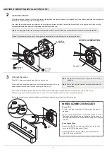
Carefully unpack the fixture. Lay out all parts on a clean
surface.
- Remove the old fixture.
Disassemble the fixture
- Twist counterclockwise to loosen the canopy screws (bb).
- Remove the mounting bracket (C) from fixture (A). Do not remove any other
parts.
SECTION A: PREPARING FOR INSTALLATION
1
2
1
SECTION B: MOUNTING INSTALLATION
Note:
To avoid damaging this product, place the components on
a soft, non-abrasive surface such as carpet or cardboard.
Fig.1
Wall Switch
Fig.2
Breaker Panel
Fig.3
Fuse Box
STEPS COMPLETED
A
Fixture
Mounting
Bracket
bb
Canopy
Screws
C


