background image

Promi SD™ User Manual ver 1.7 
www.initium.co.kr 

18


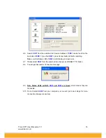
2-6.   Search 

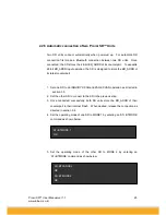
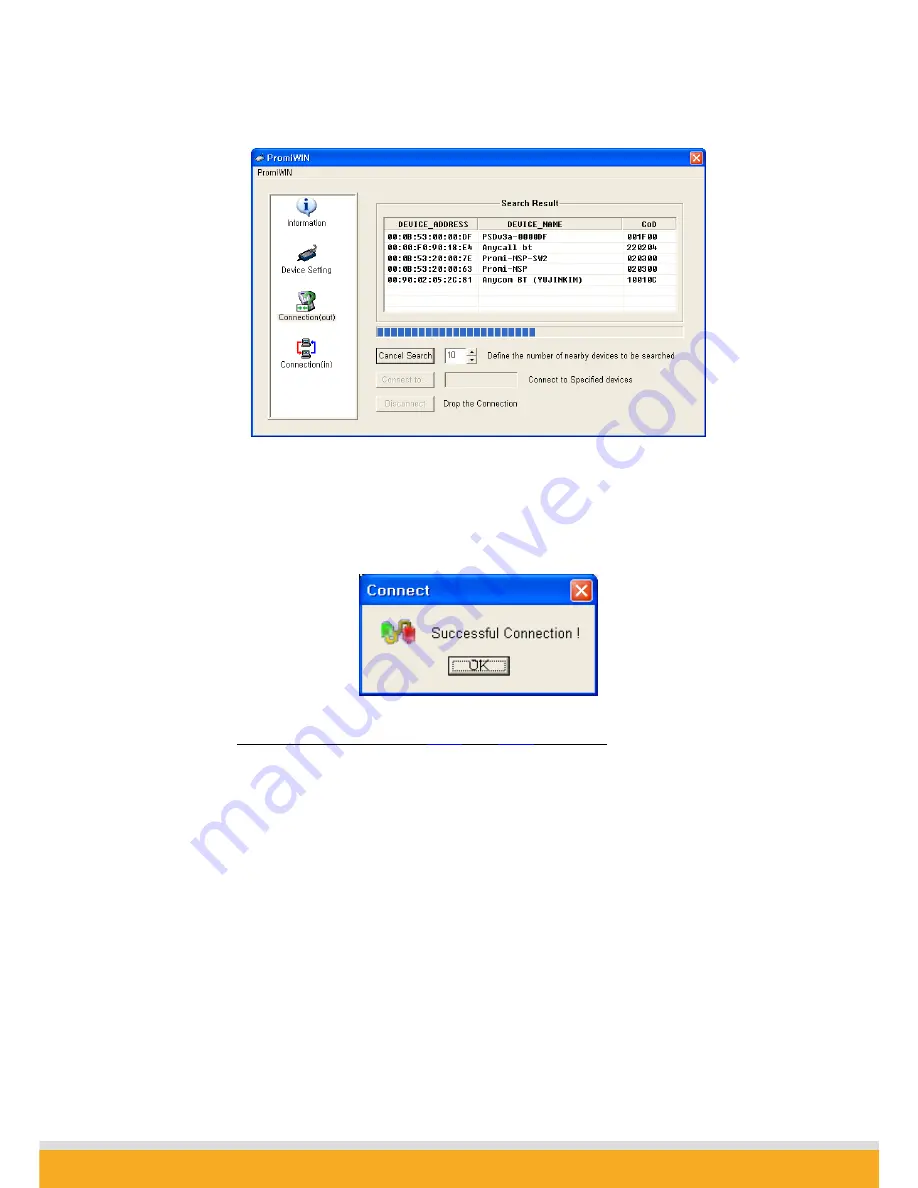
SD01

 from the searched list. Device Address of 

SD01

 can be found on the 

back side of 

SD01

. If you find 

SD01

, press Cancel button to finish searching. 

Make sure that Status LED of 

SD01

 is still blinking in Green color. 

2-7.   Please select 

SD01 

from the searched list, then press CONNECT TO button. 

2-8.     You will get Successful Connection message. 


2-9. 

    Now, Status LEDs on Both 

SD01

 and 

SD02

 are Green

, which means they are 

connected. 

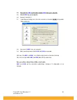
2-10. Do not detach 

SD02

 from your computer yet, we will go to next stage for Auto-

connection (Always-connection). 


Содержание Promi SD101

Страница 1: ...Promi SD User Manual ver 1 7 www initium co kr 1 by Bluetooth Enabling Wireless Serial Communications Promi SD User Manual Version 1 7 ...

Страница 2: ...ing DTR DSR CDC Release Date Promi SD101 PSDv3b 1 5 N A Sept 8 2003 Promi SD102 PSDv3b 2 0 Oct 10 2003 Promi SD202 PSDv3b 2 0 AT command Available on off Available Sept 8 2003 Note From Firmware version PSDv3b customers may choose whether to use hardware flow control using PromiWIN software If you have PSDv3b please use PromiWINver3 0b for configuration V3a Model Name Firmware version Hardware ver...

Страница 3: ...SD01 and connect to 17 2 1 3 Let s make Auto Connection between SD01 and SD02 19 2 2 Using a Terminal Program 21 2 2 1 Connecting Promi SD to host 21 2 2 2 Making the first Promi SD Bluetooth connection 21 2 2 3 Making Promi SD do INQUIRY SCAN and PAGE SCAN 23 2 2 4 Releasing the existing Bluetooth connection 24 2 2 5 Automatic connection of two Promi SD Units 25 2 2 6 AT command vs Operational St...

Страница 4: ...ls 31 OK CONNECT DISCONNECT ERROR 31 4 3 For DCE connection 32 4 4 Hardware Reset 32 4 5 How to get Bluetooth CF cards connected to Promi SD 33 5 Optional Antennas 35 6 For Multi Serial Connections 37 6 1 Promi MSP 37 7 Legal Notice 38 9 About this Manual 40 Appendix A Power Adaptor Specification 41 Appendix B AT command sets 44 ...

Страница 5: ...multipoint connections please refer to our Promi MSP providing all the features of RS485 Product line Model Name Part No Spec Promi SD101 PSD00 10100 Class 2 Output Power 2 5mW 4dBm 5V DC power supply Rechargeable Li poly Battery internal w Power Adapter w Setup Software manual on CD Promi SD202 PSD00 20200 Class 1 Output Power 63mW 18dBm 5V DC power supply w o Battery Power Adapter w Setup Softwa...

Страница 6: ... Fig 1 1 1 A CD ROM inclusive a setup software Promi WIN and user manual Fig 1 1 2 Optional Power Adaptor Part no PSD00 00010 Fig 1 1 3 USB Power Adaptor Part no PSD00 00020 You may use USB port to supply power to Promi SD using this USB power cable ...

Страница 7: ...Promi SD User Manual ver 1 7 www initium co kr 7 Fig 1 1 4 DC Power Cable Part no PSD00 00030 Red colored line of DC power cable is for ...

Страница 8: ...x 26 x 16 mm Figure 1 2 1 Promi SDTM top view Figure 1 2 2 Promi SDTM right side view Figure 1 2 3 Promi SDTM left side view Please refer to the 1 5 Power Supply section for Promi SD power options STATUS LED STUB ANTENNA P N PSD00 00040 POWER LED ON OFF SWITCH HARD RESET SWITCH DC Connector ...

Страница 9: ...ected to another Bluetooth device Green flashing STATUS LED every second indicates Promi SD INQUIRY operation Green flashing STATUS LED every 3 seconds indicates Promi SD INQUIRY SCAN or PAGE SCAN operation Amber POWER LED of Promi SD101 indicates battery is being charged Green POWER LED of Promi SD101 indicates battery is fully charged Green POWER LED of Promi SD202 indicates power is being suppl...

Страница 10: ...n PSD00 00030 Power via pin 9 of D SUB connector Promi SD101 can be recharged by 4 ways above Figure 1 5 1 DC plug polarity Promi SD101 Class2 5V 10 500mA minimum Promi SD202 Class1 4V 12V 150mA minimum Current Consumption Data at different speeds of serial communications Current Consumption Condition of Baud Rate Promi SD101 Promi SD202 Battery Life Promi SD101 9600bps 35 3 mA 40 mA 5 hrs 20 min ...

Страница 11: ... 1 7 1 Figure 1 7 1 9 PIN DSUB Female The serial interface is RS232 DCE configured a DTE device can be connected Baud rate 1200 115200 bps 230400bps for Promi SD102 202 ESD Hardware flow control RTS CTS Pin Signal Direction 1 CD Output 2 TxD Output 3 RxD Input 4 DSR Input 5 GND 6 DTR Output 7 CTS Input 8 RTS Output 9 Vcc Input Table 1 7 1 Promi SD 9 PIN Specification ...

Страница 12: ...d ATS14 Default value of ATS14 is 1 ATS14 1 cr Default setting Users may use DTR DSR lines for communications ATS14 0 cr Users may use DTR DSR lines for Loop back only ATS14 To see current status of ATS14 Default setting of CD line in Promi SD is to show the status of Bluetooth connection If users want to use CD line to send CDC signal to the other side such as for connection between Promi SD and ...

Страница 13: ...o kr 13 1 6 2 Bluetooth Interface Bluetooth Specification V 1 1 Level 4 dBm Promi SD101 18 dBm Promi SD202 Range 30m Promi SD101 100m Promi SD202 Bluetooth protocols RFCOMM L2CAP SDP Supported Profiles General Access Profile Serial Port Profile ...

Страница 14: ...nge may be used as a virtual RS 232 cable To make wireless connections between two Bluetooth devices one device should be in Discoverable INQUIRY SCAN and Connectable PAGE SCAN as well Most Bluetooth devices are set to Discoverable and Connectable in manufacture However to maximize internal battery life Promi SD INQUIRY SCAN and PAGE SCAN are disabled To make Promi SD respond to the INQUIRY and PA...

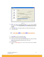
Страница 15: ...able connectable In this procedure SD01 will become discoverable connectable to be able to receive connection from SD02 1 1 Attach SD01 to your PC and start Promi WIN 1 2 Start PromiWIN then you will see a pop up window for configuration of PromiWIN Fig 1 1 1 3 Select the number of the Serial port where SD01 is attached as in the Fig 1 1 above 1 4 Users need to select exactly same Baud Parity Stop...

Страница 16: ...ring the information on the attached SD01 as in Fig 1 2 Fig 1 2 1 7 Click the Device Setting icon in the list control box Users may change the Baud rate Parity StopBit to meet their individual needs Fig 1 3 1 8 Click the Connection in icon in list control box Check both options and then click the START button as shown in Fig 1 5 ...

Страница 17: ...e its status LED is blinking green 1 11 Close Promi WIN 2 1 2 Let s make SD02 to search SD01 and connect to 2 1 Attach SD02 to your PC and start Promi WIN 2 2 Select the number of the Serial port where SD02 2 3 Users need to select exactly same Baud Parity StopBit as the setting of attached SD02 9600 No OneStopBit is default setting of all of Promi SDs 2 4 Press OK button 2 5 Select the Connection...

Страница 18: ...ish searching Make sure that Status LED of SD01 is still blinking in Green color 2 7 Please select SD01 from the searched list then press CONNECT TO button 2 8 You will get Successful Connection message 2 9 Now Status LEDs on Both SD01 and SD02 are Green which means they are connected 2 10 Do not detach SD02 from your computer yet we will go to next stage for Auto connection Always connection ...

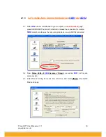
Страница 19: ...er in Connection out page press DISCONNECT button at the bottom to release the connection for a while SD02 remembers who was the last connected device even after Disconnected 3 2 Now Status LEDs of SD02 becomes Orange as well as SD01 as they are disconnected 3 3 Select Device Setting icon in the list control box and select MODE1 in Operation Mode and apply ...

Страница 20: ...ox and select MODE2 in Operation Mode and apply 3 8 Now detach SD01 from your computer 3 9 Make sure that power to Both SD01 and SD02 are supplied With two of the SD01 and SD02 turn off both using Switch on the side of its body Then turn on again Both SD01 and SD02 almost at the same time Now you will see Green Status LEDs on both units SD01 and SD02 will be connected automatically whenever if con...

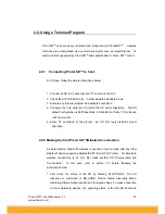
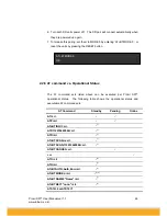
Страница 21: ...it configuration The SD default configuration is 9600 bps Baud 8 Data bit No Parity 1 Stop bit and H W flow control 5 Enter AT command at the prompt An SD OK reply indicates proper operation 2 2 2 Making the first Promi SD Bluetooth connection As stated before Bluetooth wireless connections can be made with any other Bluetooth device supporting Bluetooth SPP Serial Port Profile For Bluetooth wirel...

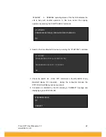
Страница 22: ...es by entering the AT BTINQ command 3 Check the search list Enter ATD command in the BD_ADDR of any Bluetooth device for connection During the connection process the STATUS LED will flash green every second 4 Connection is indicated by the SD returning a CONNECT message and displaying a green STATUS LED ATD000B53000080 OK CONNECT AT BTINQ 000B53000080 PSDv2g 000080 001F00 0004B300E205 AP2002 1 0 0...

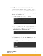
Страница 23: ...e operations must be manually activated 1 Check the SD status by entering a AT BTINFO command 2 Enter the AT BTSCAN command The SD will start INQURY SCAN and PAGE SCAN operation During the process the SD will flash twice every 3 seconds until it is connected to another Bluetooth device 3 Try Bluetooth connection to the SD from the other Bluetooth device Once connected the first SD will return the ...

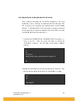
Страница 24: ... commands are treated as characters and are ignored by the command interpreter of the SD Therefore to escape from ONLINE STATUS enter escape string 1 Transition from ONLINE STATUS to STANDBY STATUS by entering string to the SD Check the current SD status by entering the AT BTINFO command The SD status should display CONNECT STATUS 2 Release the current Bluetooth connection by entering ATH command ...

Страница 25: ...ADDR of its latest counterpart 1 Set one SD to do INQUIRY SCAN and PAGE SCAN operation as directed in section 3 3 2 Set the other SD to connect to the SD in the previous step 3 Once connected successfully both SD units store the BD_ADDR of their counterpart in their internal Flash When desired release the connection as directed in section 3 4 4 Set the operating mode of one SD to MODE 1 by enterin...

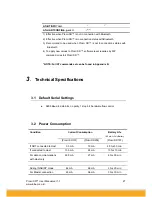
Страница 26: ... command vs Operational Status The AT command sets listed above can be executed per Promi SD operational status The following table shows the operational status and executable AT command sets AT Command Standby Pending Online AT cr ATZ cr AT BTINQ cr 1 ATD112233445566 cr 1 ATD cr 1 AT BTSCAN n cr 1 AT BTSCAN 112233445566 cr 1 AT BTCANCEL cr ATO cr 2 ATH cr 2 AT BTAUTH Auth Encr cr 3 AT BTMODE n cr...

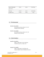
Страница 27: ...r restart Promi SD NOTE Full AT commands set can be found in Appendix B 3 Technical Specifications 3 1 Default Serial Settings 9600 Baud 8 data bits no parity 1 stop bit hardware flow control 3 2 Power Consumption Current Consumption Condition Promi SD101 Promi SD202 Battery Life 180mA Li Poly Battery Promi SD101 If NOT connected to Host 3 5 mA 19 mA 49 hrs 30 min If connected to Host 13 5 mA 24 m...

Страница 28: ...o Promi SD101 Recommended operating conditions 10 C 70 C Humidity 90 Non condensing Model No Promi SD202 Recommended operating conditions 20 C 70 C Humidity 90 Non condensing 3 4 Serial Interface Model No Promi SD101 RS232 Female DSUB 9 1200 115200 baud CTS RTS flow control or no flow control Model No Promi SD202 RS232 Female DSUB 9 1200 230400 baud Automatic Detection Feature of Hardware flow con...

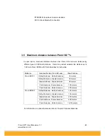
Страница 29: ...oth sides Model no Antennas for two Promi SD units Max Distance Default Antenna Default Antenna 30 meters Default Antenna Dipole Antenna 50 meters Dipole Antenna Dipole Antenna 80 meters Patch Antenna Dipole Antenna 150 meters Promi SD101 Patch Antenna Patch Antenna 300 meters Default Antenna Default Antenna 120 meters Default Antenna Dipole Antenna 150 meters Dipole Antenna Dipole Antenna 200 met...

Страница 30: ... s firmware should be set to turn OFF hardware flow control CTS RTS Customers may indicate preferences when ordering or turn off the handshaking by bridging CTS and RTS no 7 and no 8 lines using a Gender changer Version v3a has automatic detection feature of hardware flow control but in certain environment such as with PC this function may not operate well Starting from Promi SD version v3b custom...

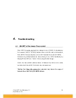
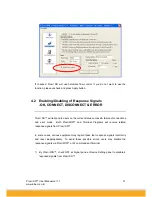
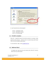
Страница 31: ...on the current status success failure of connections and error mode Both PromiWIN and Terminal Programs will receive related response signals from Promi SD In some cases various equipment may regard these four response signals incorrectly and react inappropriately To avoid these possible errors users may disable the response signals via PromiWIN or AT commands at Terminal 1 By Promi WIN check OFF ...

Страница 32: ...ion Promi SD is twisted Rx Tx ready for direct DTE connection For connection to DCE equipment such as modem etc customers need to use a gender changer which twisted Tx Rx CTS RTS DTR DSR for right operation For more information please contact support initium co kr 4 4 Hardware Reset For Hardware reset press the button on the right side of the Promi SD unit with a narrow tool such as a ball point p...

Страница 33: ... software of latest version which will be more familiar to consumers PromiWIN can be downloaded from our website at http www initium co kr english download html 1 In PromiWIN version3 start and go to the Device Setting menu 2 Select MODE3 to allow any Bluetooth device can discover and connect to this Promi SD 3 Press Apply button 4 You will get Configuration has been applied message HARD RESET SWI...

Страница 34: ... and PENDING status as in Red circle above If the Promi SD is in STANBY status connection WILL NOT be made 7 At this stage Promi SD is DICOVERABLE CONNECTABLE MODE Get your Bluetooth CF cards or USB adaptors connected to this Promi SD now Then you finish to connect your Bluetooth devices to Promi SD Open you COM port of Serial Communication program to verify communication status ...

Страница 35: ...D00 00050 2dBi Connector SMA Size 10cm 2 Patch Antenna w RF extension cable wall attachable nails Part No PSD00 00060 8 5dBi Including a 30cm RF extension cable Longer RF extension cable Part No PSD00 00061 1m length For 3m and longer length please ask it to our support initium co kr SMA connector ...

Страница 36: ...omi SD units Max Distance Default Antenna Default Antenna 30 meters Default Antenna Dipole Antenna 50 meters Dipole Antenna Dipole Antenna 80 meters Patch Antenna Dipole Antenna 150 meters Promi SD101 Patch Antenna Patch Antenna 300 meters Default Antenna Default Antenna 120 meters Default Antenna Dipole Antenna 150 meters Dipole Antenna Dipole Antenna 200 meters Patch Antenna Dipole Antenna 400 m...

Страница 37: ...onnections 6 1 Promi MSP For multiple serial connections we recommend Promi MSP Promi MSP has 7 default Bluetooth connections and can be expanded to up to 14 connections More information on Promi MSP can be found in its User Manual at www initium co kr Fig 7 1 1 Promi MSP ...

Страница 38: ...ssary authorizations for copying material The instructions for use in the manual shall not be considered as an inducement to make illicit duplications of material Any duplication will be made at user s own risk Maintenance and Support Every care has been taken in the preparation of this manual if you detect any inaccuracies or omissions please inform us by contacting Intium s technical support Ini...

Страница 39: ...VISED OF THE POSSIBILITY OF SUCH DAMAGES This warranty does not cover replacement of products damaged by abuse accident misuse neglect alteration repair disaster improper installation or improper testing FCC NOTICE THIS DEVICE COMPLIES WITH PART 15 OF THE FCC RULES OPERATION IS SUBJECT TO THE FOLLOWING TWO CONDITION 1 THIS DEVICE MAY NOT CAUSE HARMFUL INTERFERENCE AND 2 THIS DEVICE MUST ACCEPT ANY...

Страница 40: ... line and on the CD enclosed in the Promi SDTM product package For additional support related to Promi SDTM and this document contact INITIUM via INITIUM Co Ltd 716 Kumgang Hitech Valley 133 Sangdaewon Jungwon Sungnam Kyunggi 462 120 Korea Tel 82 31 777 5703 Fax 82 31 777 5704 OR www initium co kr OR Email info initium co kr ...

Страница 41: ... 4 5V 2A REGULATED OUTPUT 1 5 SHORT CIRCUIT PROTECTION 1 6 DESIGN TO MEET CLASS B LIMIT OF EN55022 AND FCC PART 15 1 7 VACUUM IMPREGNATED TRANSFORMER 1 8 100 BURN IN PROCESS 2 ELECTRICAL CHARACTERISTCS 2 1 INPUT CHARACTERISTICS 2 1 1 AC INPUT VOLTAGE 2 1 1 1 Nominal input voltage 110 220 Vac 2 1 1 2 Rated input voltage range 100 to 240 Vac 2 1 1 3 Operating input voltage range 90 to 264 Vac 2 1 2 ...

Страница 42: ...5 DI ELECTRIC WITHSTANDING VOLTAGE 2 2 5 1 Primary to Secondary 3 KV 1 Second 2 2 5 2 Cut Off Current 10mA 2 2 6 EMI 2 2 6 1 Shall be designed to meet CLASS B Limit of FCC part 15 2 2 6 2 Shall be designed to meet EN 55022 2 2 7 SAFETY 2 2 7 1 UL cUL UL1950 2 2 7 2 TUV CE EN60950 2 2 7 3 ek mark K60950 2 2 7 4 CB QAS CCIB PSE 2 3 GENERAL CHARACTERISTICS 2 3 1 OPERATING TEMPERATURE RANGE 0 C to 35 ...

Страница 43: ...i SD User Manual ver 1 7 www initium co kr 43 2 3 5 4 INPUT VOLTAGE 110 220 Vac 3 MECHANICAL CHARACTERISTICS 3 1 DIMENSIONAL SIZE LENGTH 66 mm WIDTH 48 5 mm HIGHT 35 mm 3 2 OUTPUT CABLE CABLE LENGTH 1850 50 ...

Страница 44: ...ing this AT command When your SD is already connected to the other device it disconnects the connected device You can halt the current ongoing operation by using this command AT F cr Function Restore the default configuration of your SD Response cr lf OK cr lf or cr lf ERROR cr lf Description You can restore the default configuration of your SD by executing this AT command AT BTINQ cr Function Sea...

Страница 45: ...h a Bluetooth device connected most recently Response cr lf OK cr lf cr lf CONNECT cr lf or cr lf OK cr lf cr lf ERROR cr lf Description If you execute this AT command your SD make connection with a Bluetooth device which your SD connect most recently To make this AT command work successfully there should be at least one successful connection to the other Bluetooth you want to connect AT BTSCAN cr...

Страница 46: ... until it has a connection from other Bluetooth device Your SD returns CONNECT message when it is connected from other Bluetooth device within the given time out intervals Otherwise it returns ERROR message AT BTSCAN BD_ADDR to cr Function Wait Bluetooth connection from a device with given BD_ADDR Response cr lf OK cr lf cr lf CONNECT cr lf or cr lf OK cr lf cr lf ERROR cr lf Description Once you ...

Страница 47: ...SD becomes transparent to any host applications which use serial ports ATH cr Function Release the current Bluetooth connection Response cr lf OK cr lf cr lf DISCONNECT cr lf Description This AT command can be used for disconnecting the existing Bluetooth connection AT BTSEC Authentication Encryption cr Function Set Bluetooth authentication or encryption features selectively Response cr lf OK cr l...

Страница 48: ...n to most recently connected Bluetooth device n 2 In MODE 2 your SD will wait connection from most recently connected Bluetooth device n 3 IN MODE 3 your SD does INQUIRY SCAN and PAGE SCAN alternately AT BTNAME FriendlyName cr Function Assign user friendly device name to your SD Response cr lf OK cr lf Description You can assign your SD user friendly name by using this AT command With the assigned...

Страница 49: ...Set Bluetooth Low power consumption mode Response cr lf OK cr lf Description To minimize power consumption your SD supports Bluetooth PARK mode When you set n as 1 your SD uses PARK mode Using PARK mode might cause extra data transmission delay in some cases AT BTSD cr Function Return the list of secured devices Response cr lf BD_ADDR cr lf cr lf BD_ADDR cr lf cr lf BD_ADDR cr lf cr lf OK cr lf De...

Страница 50: ...Function Configure the serial port of your SD Response cr lf OK cr lf Description By using this AT command you can reconfigure the serial port of your SD You can set baudrate parity stopbit To make this command result active you should do soft reset or turn off on your SD The following values are permitted for each parameter Baudrate 1200 2400 9600 19200 38400 57600 or 115200 230400 only for Promi...

Страница 51: ...es The OK at the end means end of inquiry 5 ATD112233445566 cr cr lf OK cr lf cr lf CONNECT cr lf or cr lf ERROR cr lf Connect to the specified device If you want to enable Authentication and Encryption just set variable as 1 6 ATD cr cr lf OK cr lf cr lf CONNECT cr lf or cr lf ERROR cr lf Connect to the device that last succefully connected 7 AT BTSCAN cr cr lf OK cr lf Enable inquiry and page sc...

Страница 52: ...onnected device 16 AT BTMODE n cr cr lf OK cr lf Sets the mode of device If n 0 device operates at Standart mode which accepts all AT commaned supported If n 1 device operates at Master mode which try to connect peer device If n 2 device operates at Slave mode which waiting for connection If n 3 device operates at always connectable mode 17 AT BTNAME FriendlyName cr cr lf OK cr lf Sets the friendl...

Страница 53: ...e paring when connecting as master 25 AT UARTCONFIG baudrate parity st opbit handshaking cr cr lf OK cr lf Sets the configuration of UART interface Possible values are baudrate 1200 4800 9600 19200 38400 5760 0 or 115200 parity N o parity E ven parity or O dd parity stop 1 or 2 Handshaking 1 or 0 If 1 hardware handshaking will be used If 0 handshaking function of Promi SD will be turned off 26 AT ...

Страница 54: ...me during Inquiry If set as 0 only get BD address Inquiry time can be faster 31 ATS10 Default 1 ATS10 1 cr Enabling all of the response messages OK CONNECT DISCONNECT and ERROR ATS10 0 cr Disabling all of the response messages OK CONNECT DISCONNECT and ERROR ATS10 cr To see current status of ATS10 32 ATS11 Enable Escape default 1 Escape sequence character enable change from on line mode to command...

Страница 55: ... set ATS15 1 users may use DTR signal to disconnect Bluetooth connection If ATS15 1 and DTR signal is changed from state ON to OFF your connection will be disconnected ATS15 0 cr If ATS15 0 users may NOT use DTR signal to disconnect the Bluetooth connection 37 ATS24 Maximum number of inquiry result default 10 38 ATS29 Error Code for last occurred error Users can not change this value 39 ATS31 Page...

Отзывы: