Promi SD™ User Manual ver 1.7
www.initium.co.kr
12
Promi SD™ is designed to operate as DCE (Data Communications Equipment).
To connect to DTE (Data Terminal Equipment), for example a PC or a laptop, a
straight cable must be used as in below.
CD, 1
CD, 1
TxD, 2
RxD, 2
RxD, 3
TxD, 3
DSR, 4
DTR, 4
GND, 5
GND, 5
DTR, 6
DSR, 6
CTS, 7
RTS, 7
Promi SD (DCE)
RTS, 8
CTS, 8
Host
S
yst
em (DTE
)
*DTR/DSR of Promi SD™ will be functioned for either Loop-back operation or
for full transfer. Users may select a function of DTR/DSR using AT command-
ATS14.
Default value of ATS14 is 1.
ATS14=1<cr>: Default setting. Users may use DTR/DSR lines for
communications
ATS14=0<cr>: Users may use DTR/DSR lines for Loop-back only.
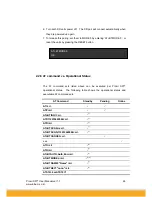
ATS14?: To see current status of ATS14.
*Default setting of CD line in Promi SD is to show the status of Bluetooth
connection. If users want to use CD line to send CDC signal to the other side,
such as for connection between Promi SD and DCE device, users need to
configure ATS13.
ATS13=0<cr>: Default setting. Users may use CDC line for checking
Bluetooth connection
ATS13=1<cr>: Users may receive CDC signal from other Promi SD.
(This function will be available from future version of
Promi SD for DCE devices)
ATS13?: To see current status of ATS13.


