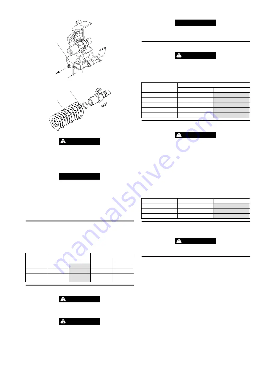
4
1
S
(Dwg. MHP3333)
3
2
(Dwg. MHP3334)
CAUTION
•
Should the brake magnet (1) hum, buzz or vibrate, then the air gap (S) must
be reset in accordance with Table 4 ‘Brake Air Gap (DC Brake)’
•
If the lifting speed is only reached slowly or the load drops a little further
after it has been lowered, this is a sign of oily or sticky brake discs (2) or the
closing of the disc cage (3). Dismantle brake discs, clean and degrease. Disc
cage to be replaced if damaged.
NOTICE
•
By releasing the disc brake [carefully pull on the brake arm (4)] the load can
be lowered in a manual mode.
•
Replace brake discs if they are distorted or severely discolored.
1. Turn nut (5) or (7) until the ‘S’ gap (refer to Table 4 ‘Brake Air Gap (DC Brake)’
2. Push brake solenoid in and rotate cup disc (11) with fingers. Disc should rotate
with a little drag. Loosen nut on capscrew (8). Adjust capscrew until disc rotates
with a little drag. If cup disc is too loose the brake will chatter or hum during
operation.
3. Repeat steps 1 and until ‘S’ gap is correct and disc cup just rotates.
n
Brake Test
1. Use a test load that is 100% of hoist capacity.
2. With cover off, hoist load, in low speed mode, approximately 1 ft. (0.3 m).
3. Listen to brake while hoisting.
4. When hoisting stops, brake should hold load.
Table 4: Brake Air Gap (DC Brake)
Brake type
Brake Air gap ‘S’
Number of discs
(inch)
(mm)
internal
external
QCH50
0.080
2.00
5
5
QCH100
0.080
2.00
7
7
QCH2
00/300/500
0.080
2.00
8
8
n
Load Chain
WARNING
•
Before conducting maintenance on the hoist, lower and remove suspended
load. Disconnect electrical supply and remove hoist from overhead
suspension.
CAUTION
•
The chain is to be replaced when the measurements exceed those defined
in the Table 2 ‘Load Chain’ on page 3. The chain wheel and chain guide are
to be checked for wear at the same time, and, where necessary are to be
replaced.
•
Only original chains are to be used. The chain links are not to be welded.
NOTICE
•
For ease of installation, do not remove the old chain from the hoist. The old
chain can be used to feed the new chain through the hoist by connecting
them with a “C” link.
n
Limit Stop Assembly
CAUTION
•
Defect spring elements and rubber buffers are to be replaced.
Screw connections at the limit stop and shims at lower sheaves are to be checked
and, where necessary, tightened to the right torque. For torque values see Table 5.
Table 5: Torque Values
Dimension
Torque
lbs-in
N-m
M5
53
6
M6
88
10
M8
212
24
M10
425
48
M12
732
83
n
Gears
CAUTION
•
Use extreme care when removing gear end cover to avoid grease spillage.
The gear compartment is filled with grease at the factory to provide continual
lubrication. Replacement of the grease for the life of the hoist should not be required.
n
Lubrication grease:
Strub N142 4
Compatible with Type DIN 51502 : GP OM-2
If it becomes necessary to remove the gear end cover, first ensure the hoist body is
standing on end with the gear end cover up. Failure to observe this procedure will
allow the grease to flow from the hoist. Whenever the gear end cover is removed,
always replace the cover gasket. For quantity refer to Table 6.
Table 6: Gear Case Greasing Quantity
Model
lbs
kg
QCH50
0.88
0.40
QCH100
2.20
1.00
QCH200/300/500
4.00
1.80
n
Slip Clutch
The slip clutch is pre-adjusted. The lining is wear resistant.
CAUTION
•
An adjustment of the slip clutch may only be effected by qualified personnel
and must be entered in the inspection pass.
n
General Overhaul
On reaching the theoretical service life (no later than 10 years for collection without
BDE), a general overhaul is to be performed. Hereby the device is put into a condition
allowing a safe operation within another period of utilization (service life).
For this, components according to Table 7 must be inspected and/or exchanged.
The inspection of as well as the approval for further utilization must be performed
either by an expert company authorized by the manufacturer, or by the
manufacturer personally.
The inspector determines:
- the new possible theoretical utilization
- the max. period until the next general overhaul
Such data is to be documented in the inspection report.
Form 16586737 Edition 4
7
Содержание QCH100
Страница 10: ...www ingersollrandproducts com...


