MAINTENANCE
WARNING
•
Never perform maintenance on the hoist while it is supporting a load.
•
Before performing maintenance, tag controls:
WARNING - DO NOT OPERATE -
EQUIPMENT BEING REPAIRED.
•
Only allow personnel trained in service and repair of this hoist to perform
maintenance.
•
After performing any maintenance on the hoist, test hoist before returning
hoist to service.
•
Turn off and lockout/tag out electrical disconnect switch before performing
any maintenance.
•
The lower sheave block or hook assembly must be lying on the floor or a
maintenance platform before beginning service.
n
General Maintenance Instructions
NOTICE
•
It is recommend that maintenance work be performed by an Ingersoll Rand
service repair center.
•
If the operator performs maintenance work on an electric chain hoist on his
own account, the type of maintenance performed must be entered together
with the date of performance into the inspection pass.
All maintenance work performed on the hoist must be recorded with the date in the
inspection report.
Alterations to, as well as changes of and supplements to the electric chain hoists
which may impair the safety must be authorized by Ingersoll Rand in advance.
Constructional alterations to the chain hoists not authorized by the Ingersoll
Rand lead to an exclusion of the manufacturer’s liability in case of damage.
Material warranty claims will only be recognized if solely genuine spare parts by
Ingersoll Rand have been employed.
We explicitly wish to point out that original parts and accessories not supplied on
our behalf cannot be inspected or released by us.
Proper use, inspections and maintenance increase the life and usefulness of your
Ingersoll Rand equipment. During assembly, lubricate gears, nuts, capscrews and
all machined threads with applicable lubricants. Use of antiseize compound and/or
thread lubricant on capscrew and nut threaded areas will help to prevent corrosion
and allows for ease of disassembly of components.
It is recommended that all maintenance work on the hoist be performed on a bench
in a clean dust free work area. During the process of disassembling the hoist, observe
the following:
1. Turn off and lockout/tag out electrical disconnect switch before performing any
maintenance. Disconnect electrical cable from hoist.
2. Never disassemble the hoist any further than is necessary to accomplish the
needed repair. A good part can be damaged during the course of disassembly.
3. Never use excessive force when removing parts. Tapping gently around the
perimeter of a cover or housing with a soft hammer, for example, is sufficient to
break the seal.
4. Do not heat a part with a flame to free it for removal, unless the part being heated
is already worn or damaged beyond repair and no additional damage will occur
to other parts.
NOTICE
•
In general, the hoist is designed to permit easy disassembly and assembly.
The use of heat or excessive force should not be required.
5. Keep the work area clean to prevent dirt and other foreign matter from getting
into bearings and other moving parts.
6. All seals and O-Rings should be discarded once they have been removed. New
seals and O-Rings should be used when assembling the hoist.
7. When grasping a part in a vise, always use leather or copper covered vice jaws
to protect the surface of the part and help prevent distortion. This is particularly
true of threaded members, machined surfaces and housings.
8. Do not remove any part which is press fit in or on a subassembly unless the
removal of the part is necessary for repairs or replacement.
9. To avoid damaging bearings during hoist assembly or disassembly always tap
or press on the bearing inner race for shaft fit bearings or the outer race for bore
fit bearings. When removing bearings from housings, drive out the bearing with
a sleeve slightly smaller than the outside diameter of the bearing. The end of the
sleeve or pipe that is used to contact the bearing must be square. Protect
bearings from dirt by keeping them wrapped in clean cloths.
10. If repair work can only be conducted above body height, suitable working
platforms or ladders should be made available.
11. Work on electrical equipment or machinery may only be conducted by licensed
electricians or persons under the supervision and guidance of licensed
electricians, in accordance with all appropriate electrical codes and regulations.
WARNING
•
All new, altered or modified equipment should be inspected and tested by
personnel trained in safety, operation and maintenance of this equipment
to ensure safe operation at rated specifications before placing equipment
in service.
Inspection procedures for hoist in regular service are divided into two general
classifications based upon the intervals at which inspection should be performed.
The intervals in turn are dependent upon the nature of the critical components of
the hoist and the degree of their exposure to wear, deterioration or malfunction.
The two general classifications are herein designed as frequent and periodic. The
inspection intervals recommended in this manual are based on intermittent
operation of the hoist; that is, eight hours per day, and five days a week, in an
environment relatively free of dust moisture and corrosive fumes. If the hoist is
operated with a greater run time per shift or more than eight hours per day the
inspection interval must be reduced. Refer to ASME B30.16 for specific time period.
Careful inspection on a regular basis will reveal potentially dangerous conditions
while still in the early stages, allowing corrective action to be taken before the
condition becomes dangerous.
Deficiencies revealed through inspection, or noted during operation, must be
reported to designated personnel trained in safety, operation and maintenance of
this equipment. A determination as to whether a condition constitutes a safety
hazard must be decided, and the correction of noted safety hazards accomplished
and documented by written report before placing the equipment in service.
n
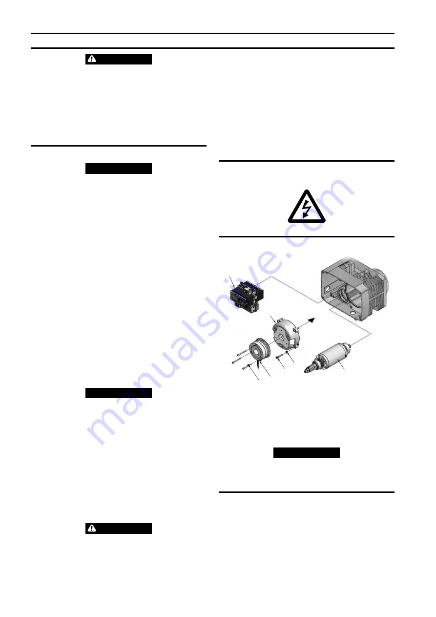
Cover Removal
Electrical side is indicated by Symbol.
(Dwg. MHP3349)
n
Brake System (AC Brake)
4
5
7
6
3
2
1
(Dwg. MHP3332)
n
Assembly
1. Install the rotor shaft (3) into the housing.
2. Install the motor cover (2) into the housing. (Preheat the Cover if necessary).
3. Insert the spring washer (6), and tighten the allen screw (7) and torque to 6-10
Nm.
4. Place the brake assembly on the motor cover.
5. Insert allen screw (5) and tighten to torque 3-10 Nm.
NOTICE
•
Play Check the brake assembly and adjust if necessary.
6. Fit the adjusting screw (1).
7. Install the control assembly (4). Refer to “WIRING DIAGRAM” on page 8 on
pages 9 and 10.
n
Brake System (DC Brake)
In the power free mode, the brake must be able to hold the nominal load without
any problems. It has been operationally adjusted before delivery.
6
Form 16586737 Edition 4
Содержание QCH100
Страница 10: ...www ingersollrandproducts com...


